U.FL connectors have replaced pinheaders used on nihtila.com boards so let’s start with some reasoning behind the change.
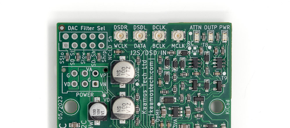
Why we switched to U.FL cables
While some probably prefer good old pinheaders, they are not very sound way of distributing clock signals and digital audio, especially if a spaghetti of wires is soldered in the headers. Yes it works, at least most of the times, but why not do it with better quality connectors and cabling which is easily available for good price?
U.FL cables are tiny and high bandwidth yet affordable cables used typically in high bandwidth consumer applications like connecting a Wi-Fi antenna to a PCB. They are not meant for repeated mating like their larger and sturdier RF-counterparts seen on front and rear panels such as BNC or SMA; however, U.FL suit well inter-board connections. They ensure better signal integrity (albeit we are not using impedance matched transmission lines) and interference performance than pinheaders and flat cables, while still retaining a small footprint.
U.FL reliability
U.FL cables or connectors do not break easily although it may feel like it at first. However, they are still tiny and rather flimsy compared to larger connectors so don’t use excess force when pushing, pulling or bending them. Make sure the connectors are aligned when connecting, and be gentle with pulling/bending when disconnecting. Despite all prototyping, measurements, testing, modifications etc. across all the new Kaamos Tech boards using U.FLs, we have not had a single connector or cable failure.
Connecting U.FL cables to pinheaders
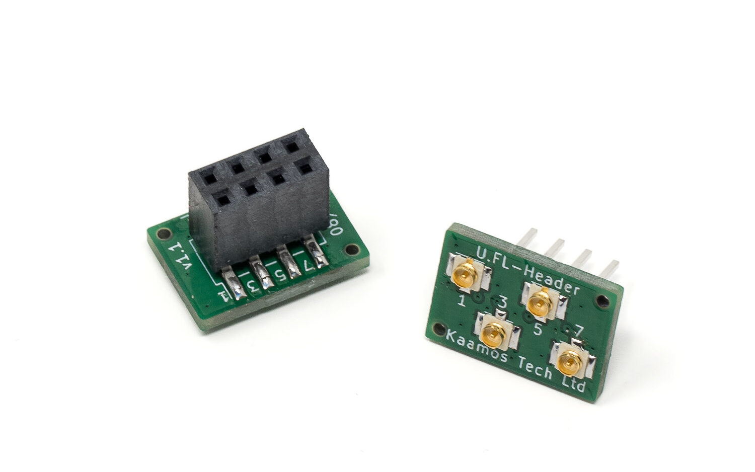
U.FLs are used throughout the Kaamos boards but what if you want to interface to an older nihtila.com board or a board made by someone else?
U.FL to header adapters
To offer the easiest possible solution, we are selling tiny adapters that stack on a male or female pinheader and have four U.FL connectors. These should work with most devices but they do require that all the signals are in adjacent pins and have an adjacent row of ground pins. If that’s not the case, you may be able to use another raiser header with bent pins to mate the required pins, or solder short cables to the adapter.
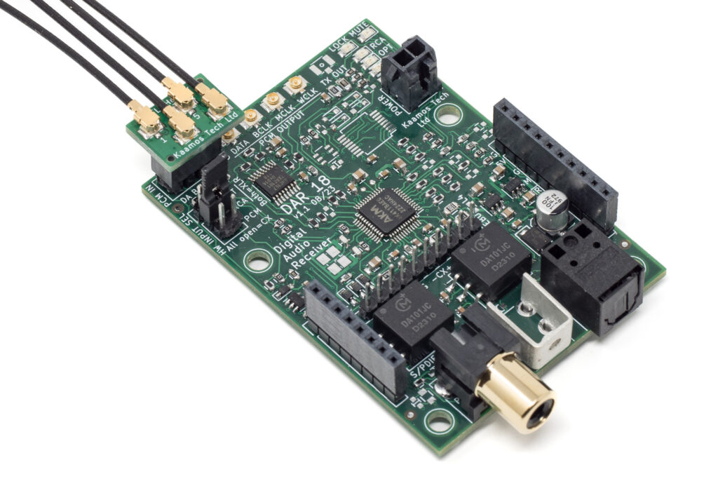
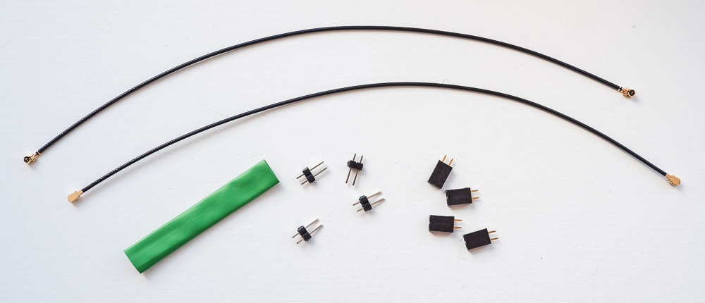
Make U.FL to header cables
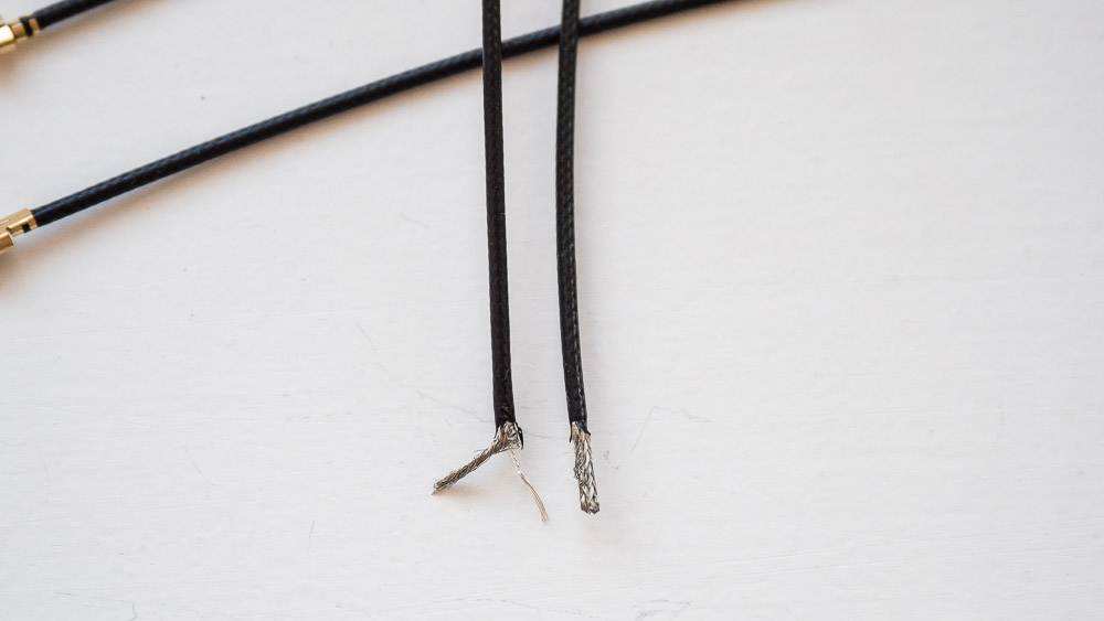
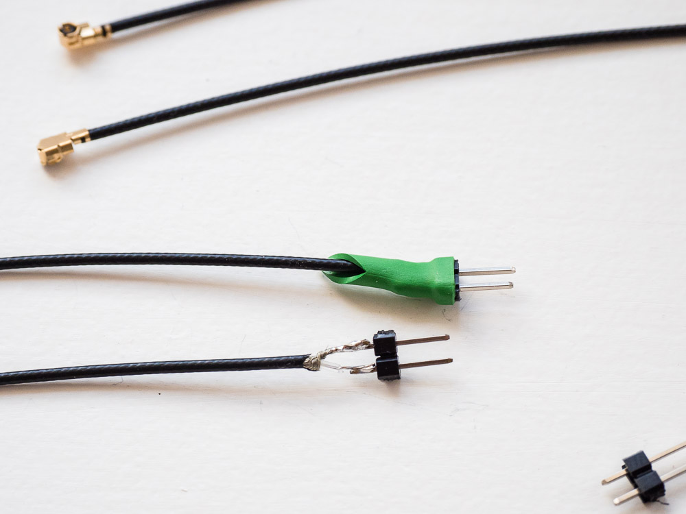
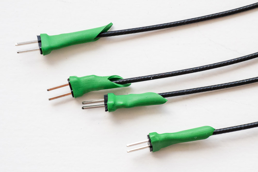
Another easy sounding option is to take a U.FL cable, cut it into two and solder headers at the end. It is definitely doable; however, U.FL cables are very thin and stripping and soldering them is not easy. The cables we sell are ‘thicker’ U.FL cables but still very thin, and that includes the outer jacket, shield, dielectric, and center conductor. Below are pictures of modified U.FL cables but we do recommend using the header adapters if possible. We also made a small flaw with these modified cables because the heat shrink is fairly thick, it is difficult to fit many of these into adjacent header pins.