
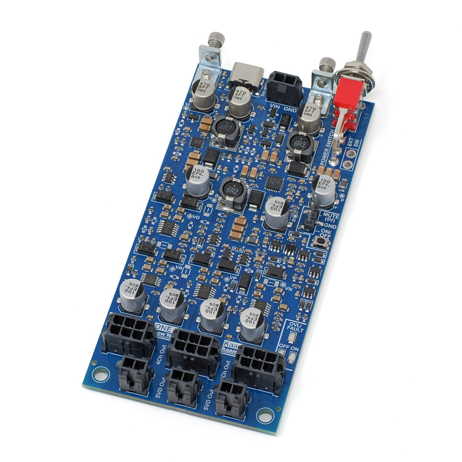
The following is additional information on using Kaamos One Four All power supply board. Please also see the product description. If something is still unclear, please contact us. We will try to update the information based on feedback.
This guide has been updated for OFA v2 (blue PCB) but also applies to v1 (green PCB).
The concept
One Four All (OFA) is a high-quality all-in-one power supply that generates four supplies from a single 5V input. It has multiple power outputs to easily power several Kaamos (or other) audio boards. In addition, the board provides comprehensive protection and safety features for increased reliability and robustness – and peace of mind.
In the heart of the design are three switching converters: two boosts and one inverter. The switched voltage rails are filtered with snubbers and CLC-filters designed based on lots of measurements, and the final output power rails are provided by very high-performance LT30xx linear regulators (one for each rail) with very high and wide-bandwidth PSRR and low noise.
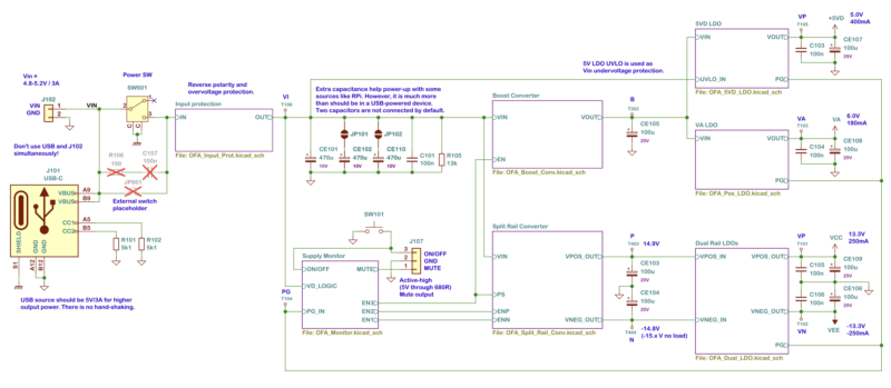
The board can be supplied by a generic USB-charger, or power bank for isolated power. The PSU is not sensitive to input power noise and interference as the input goes through the converters, filters, and LDOs; a dirty 5V input does not mean dirty 5V output since it’s a completely new rail. Nevertheless, a decent quality input supply is still preferred to avoid any issues, mainly with power-up.
Power outputs
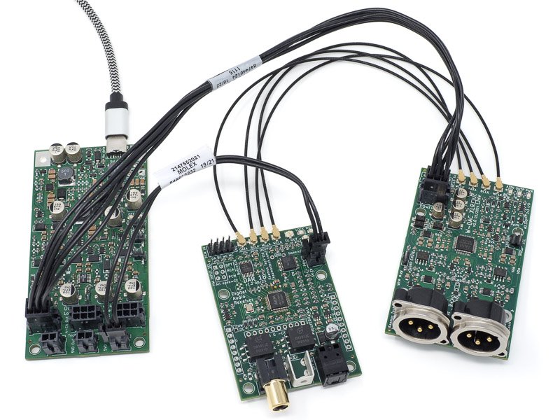
There are two types of Molex Micro-Fit output power connectors with following supplies:
- 2-pin digital-only power output:
- VD (5V digital).
- GND.
- 6-pin mixed-signal power output:
- VD (5V digital).
- VA (6V analog reference).
- VP (+13.3V analog amplifier/opamp supply).
- VN (-13.3 analog amplifier/opamp supply).
- Two GND pins.
OFA has three output connectors (in parallel) of each type to power up to six boards, given that the following total output currents are not exceeded:
- VD: 400mA.
- VA: 150mA.
- VP: 250mA.
- VN: 250mA.
Not all rails should be loaded to the maximum output, or this may lead to the converters reaching over 100C temperatures.
Each supply rail is equipped with a current-limit and under-voltage monitor. In an overload situation the current limits drops the voltage which triggers an under-voltage event, turning the rail off. When any one rail turns off, they all turn off and the PSU goes to OFF (standby) state.

Power input
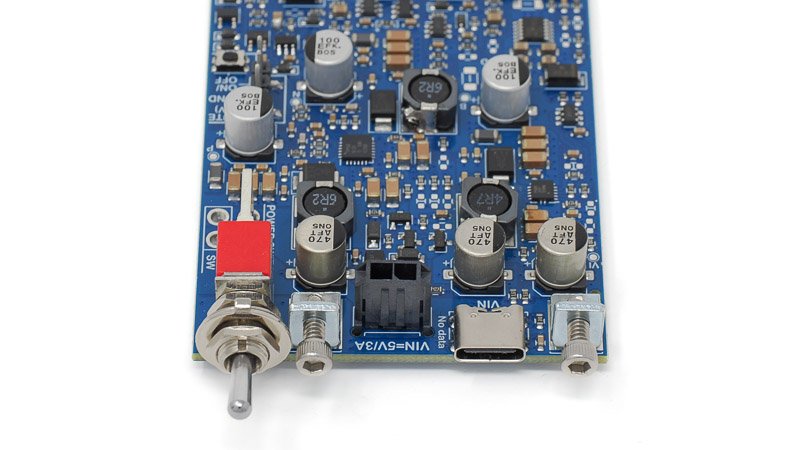
Power input is 5V via USB-C, Molex input connector, or wires soldered onboard. We have specified the input voltage range as 4.8-5.2V. It can be a little higher but overvoltage protection kicks in somewhere around 5.5-6.0V. Higher voltage means less stress and heat in the converters when operated at higher output currents; therefore, a voltage slightly over 5V can be beneficial. Some USB-C 5V power supplies may be 5.1V or 5.2V to compensate some of the voltage drop in the cable.
We have successfully used official Raspberry Pi 3A (27W model) and 5A (45W model) supplies in our tests; while we don’t need 5A current the latter keeps the voltage slightly higher under load.
To use your own 5V source, the input Molex cable makes wiring easy.
Board input voltage and wires
The board takes significant current from the 5V input supply and there is always a voltage drop due to wiring resistance. If the board is heavily loaded, the input wires should be thicker and shorter. The board input voltage can be measured under full load to see how much it drops. It is recommended to keep the board input over 4.7V. If the input drops under 4.3V (exact limit depends on the current), the board turns off.
Power switch
We always recommend turning the board off completely when not in use. OFA v2 has an onboard power switch, or an external ON-OFF switch can be wired out to a more convenient location. OFA v1 only has a placeholder for an external switch, which is shorted by default. As any power switch is in series with the input and carrying all the input current, the switch and its wires must have low enough on-resistance to meet the board input voltage requirement. Any external switch must be rated for 3A DC or higher.
Input current
The PSU can take up to 3A of input current when fully loaded. Even if not fully loaded, the input supply should have sufficient current rating due to inrush current. A 5V/2A supply is sufficient for most use cases but higher loading requires a 3A supply; see examples below and leave some headroom. There is no USB-handshaking; OFA has sense resistors to tell the host it needs up to 3A current but does not check if the source can support that.
The following input supply currents are guidelines, the exact voltage at the board input has impact on the current (higher voltage drop = lower input voltage = higher input current).
- Outputs on, no load: 90mA.
- Outputs off (standby): <2mA.
- VD 100mA, VA 100mA, VP/VN 100mA each: 1.2A.
- VD 200mA, VA 100mA, VP/VN 200mA each: 2.2A.
- It is normal the board gets very warm under this loading; the hottest components can get near 80C – and even hotter if loaded closer to the maximum. VP/VN loading stresses the board more than VD/VA loading.
For reference, Kaamos converter boards take approximately:
- W-DAC v3:
- VD 40mA, VA 40mA, VP/VN 40/40mA.
- ADC AK5572 v2:
- VD 15mA, VA 30mA, VP/VN 70/70mA.
Therefore, one OFA can power multiple boards.
OFF / Standby
OFA has a standby mode noted by OFF led. The power-up follows a state machine where the three converters are turned on in sequence to lower the inrush current. Transition between ON and OFF states are engaged with an (ON)-OFF ‘soft’ power buttons. In OFF state all outputs are off (0V) but the PSU logic remains on.
The idea is the same but there are some differences between OFA v1 and v2.
ON/OFF button (OFA v2)
A single ON/OFF button toggles the PSU between ON and OFF. Besides the onboard button, an external button can be wired between the ‘GND’ and ‘ON/OFF’ pins of the header (shorting them). It is only for a logic signal and can be a small signal switch with thin wires.
Due to limitations of the already complex hardware state-machine, when toggling from OFF to ON and keeping the button depressed for longer than around 1 second, the PSU toggles back from ON to OFF.
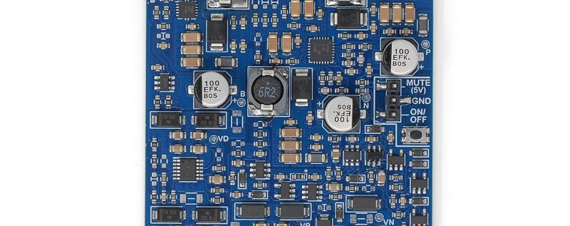
Single ON/OFF button on the right edge, or external button between ‘ON/OFF’ and ‘GND’ on header.
Soft-stop and soft-start (OFA v1)
Soft-stop puts the PSU in standby and soft-start turns it back on. These can be engaged with external push-button (ON)-OFF type switches connected to Start and Stop header solder pads.
The PSU turns on all outputs upon power-up and can be turned off by a hard power switch or unplugging the input; therefore, soft switches are optional.

Mute output
Mute Out is active-high with 5V (around 4.8V in OFA v1) level when the PSU is in OFF/standby state. It can be connected to W-DAC EMUTE input, for example, to quickly mute the output if power turns off (as the DAC already has its own power monitor mute, this may not make any difference).
Power-up state
Upon power-up, the PSU turns ON automatically. All output channels (5V, 6V, +/13V) are turned on in a sequence to minimise start-up current spike. Successful ON-state is signalled by the ON LED. MUTE output is low.
In OFA v2 the default power-up state can be changed to OFF/standby by shorting a link on the bottom side of the PCB. After power-up, engaging the ON/OFF power button (or header) turns the PSU ON.
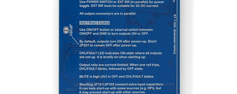
Short JP201 to remain OFF after power-up.
OVL/FAULT led (OFA v2 only)
OVL/FAULT signals a state where the PSU tries to be ON but there is a fault in the outputs. It is normal it to blink when transitioning between OFF and ON. This state should never be longer than a blink since any fault should turn off the outputs and go to OFF state.
Mounting hardware
OFA has a mounting hole on each corner of the PCB like other Kaamos boards. Normal standoffs can be used on each corner but we also provide small L-brackets for panel mounting. The L-bracket pads and holes are plated with low-inductance connection to the casing of the USB-connector.

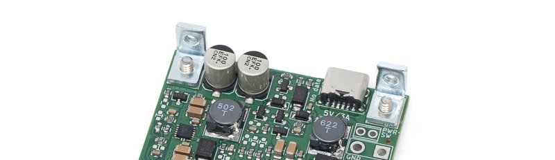
Note that the mounting hole locations are different in OFA v2; the PCB is also larger.
Startup issues
Due to extensive protection features and some dependency on the input 5V supply, the PSU may fail to power up under certain conditions. This is indicated by OFF-LED after power-up. There are quite significant differences between OFA v1 and v2 in the startup behaviour; v2 has a longer power-up sequence that should take care of most startup issues.
Note that connecting a load with significant capacitance when the PSU is ON expectedly turns it off. This is simply because a high capacitance momentarily triggers the output overcurrent protection – as intended. When starting up, there is a delay until the overcurrent protection becomes active to allow load capacitances to charge. The delay is significantly longer in OFA v2.
Extra input capacitance (OFA v2 only)
Input capacitance has been increased from 200uF in v1 to 470uF in v2. Moreover, there are two additional 470uF capacitors that are disconnected by default; even 470uF is quite high capacitance for USB supplies. However, with some power sources like Raspberry Pi (tested with RPi 5), the extra capacitance is required to power up; otherwise the PSU ends up in a slow oscillation where RPi turns the USB power on and off.
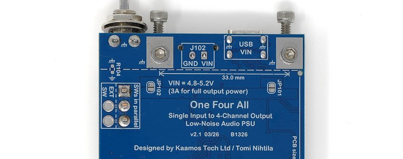
Short JP101 and/or JP102 to add more input capacitance, 470uF each.
Startup troubleshooting steps
These are mainly meant for OFA v1 due to improvements in v2, but some advice still apply.
Too low input voltage may cause a startup failure. This can occur due to several reasons:
- Input voltage supply is too low.
- Worth checking but this is unlikely the case if using a 5V supply.
- High input wiring and/or power switch resistance. Too high series resistance causes the input voltage to drop too much at power-up when the PSU loads the input. There is always an inrush current at start-up as well that makes the input voltage momentarily lower than steady-state loading.
- What is too high resistance? It depends on the loading. We recommend aiming to keep the board input voltage at 4.7V under load. With lighter load it should work down to 4.3V but this gives some headroom for heavier loads.
- Input supply current limit. The above-mentioned startup-droop gets worse if the input supply cannot provide sufficient startup current. Hence we recommend at least 2A 5V supply even with light loads.
- If you think the input wiring resistance is low enough, please try another USB-supply. How fast and hard the current limit of a supply is varies by model.
Another source of failure may be due to output supplies not reaching their final values within the startup sequence time (200ms in v1, 1000ms+ in v2) because of:
- Too high load current. If the output current limits are exceeded, outputs are turned off.
- Check combined output load current and see the limits are not exceeded. Check that connected boards are working fine, maybe one at a time.
- Too high load capacitance. As all output channels are current-limited, charging high capacitances take time, causing voltages to go up too slowly.
- What is too high capacitance? It depends on the combination of capacitances in each output channel and overall DC-loading. If the DC-loading is low (e.g. VD uses 100mA out of available 400mA), there is more current available to charge the capacitances than if we are already near the current limit (e.g. DC-loading 350mA out of 400mA). We have tested the PSU with 1000uF on each channel (VD, VA, VP, VN) at moderate loading successfully. At low loads the capacitances can be higher, but being close to the limit this may be too much.
Other questions
Can I use OFA with a 4.2V Lithium battery?
As it is now, no. Currently the input under-voltage shutdown engages at around 4.1V. We have evaluated the performance down to 3.5-3.2V what it should support in such case. Some output channels work fine but VN struggles especially if input voltage drops slightly. With minor changes (maybe just a different BOM) we could make a variant with significantly lower output current capability (likely to power only one ADC or DAC) that supports Li-Ion use. If you are interested in such use case, please let us know. No promises but if there is enough interest, we’ll look into it. Some of the work is already done. Note that any battery management circuitry would need to be external.
2 comments
Hello Tomi,
I like this concept to power up my audio electronics from a single 5V (USB / Powerbank) Source.
do you have some noise figures (and other performance figures) measured ?
e.g. xx µV RMS (@ 20 Hz – 20 kHz BW)
line- and load-regulation etc…
I wonder if I could even replace my power supply for my (very sensitive) phono preamp with this solution ?
For the future, I would like to have a slimmed-down version that only has +/-15V connections (perhaps with an additional mute connection).
Hi Dirk. Unfortunately not yet, summer took time away from this.. But I am back at it, I have a set of half-ready OFA boards to finish and I will also try to sort out the measurement results. Expect updates within the next 2 weeks.
Briefly, I don’t see line regulation an issue here as there is a switcher and an LDO; something quite horrendous needs to happen at the input to be measurable at the output. You do see a tiny load regulation step due to PCB trace resistance. I mainly need to better characterise the noise and switching noise – which is always there even if very small.
Stripped-down version could be possible if there is enough interest. There is active-high Mute output.