SPDIF TX v2 – I2S to S/PDIF Converter
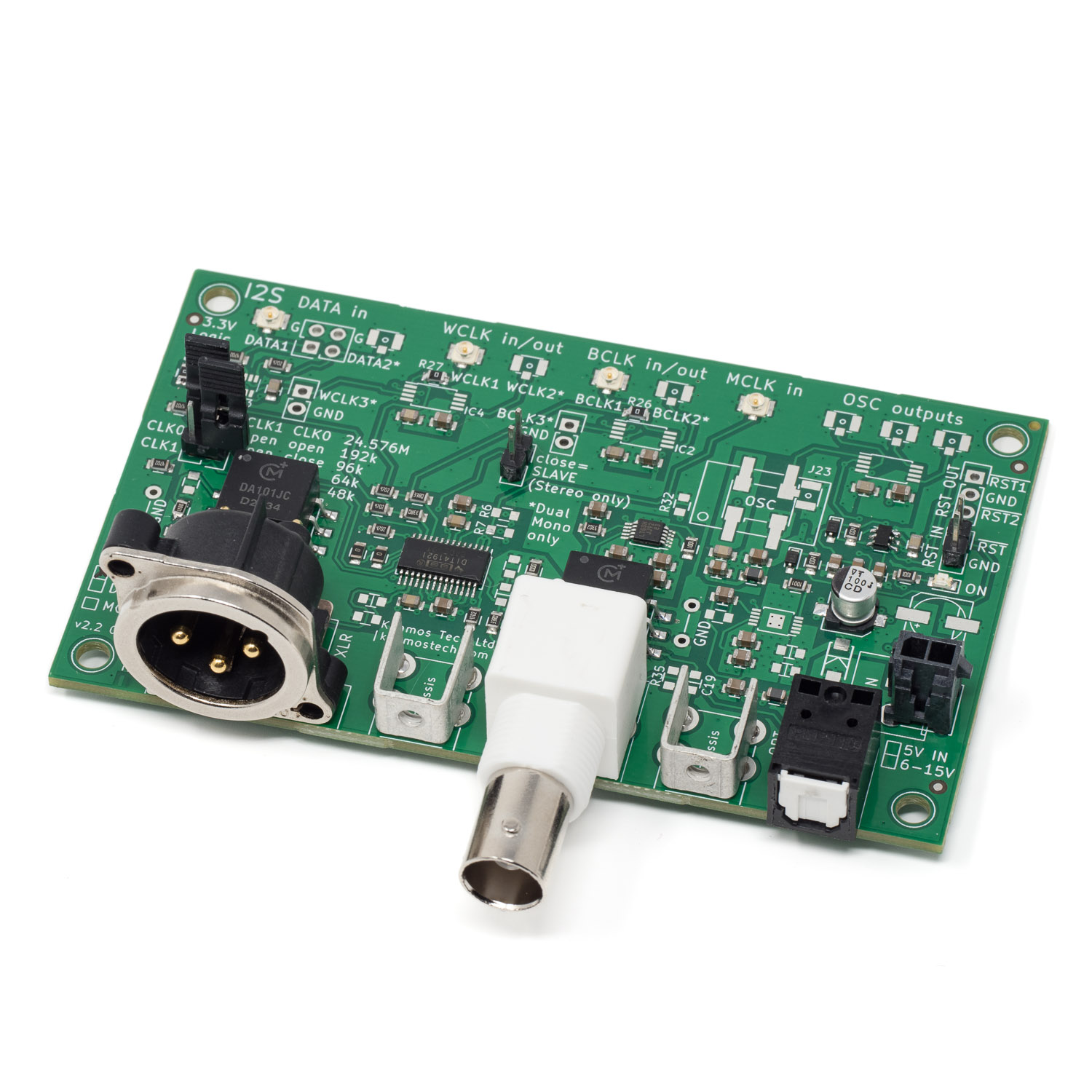
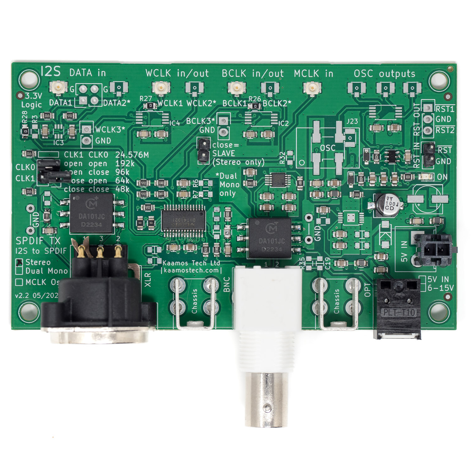
PCM I2S to S/PDIF digital audio converter with I2S serial audio input and BNC, Toslink, and AES/EBU outputs.
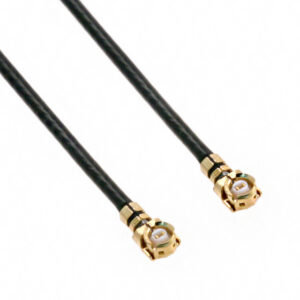
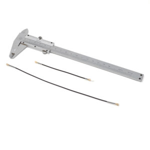
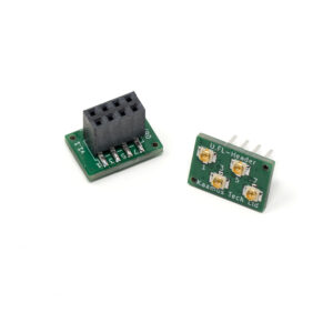
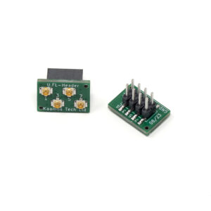
- I2S input via U.FL connectors
- I2S Master or Slave
- Three S/PDIF outputs: BNC, Toslink, and XLR (AES/EBU)
- All outputs galvanically isolated
- All outputs can be used simultaneously
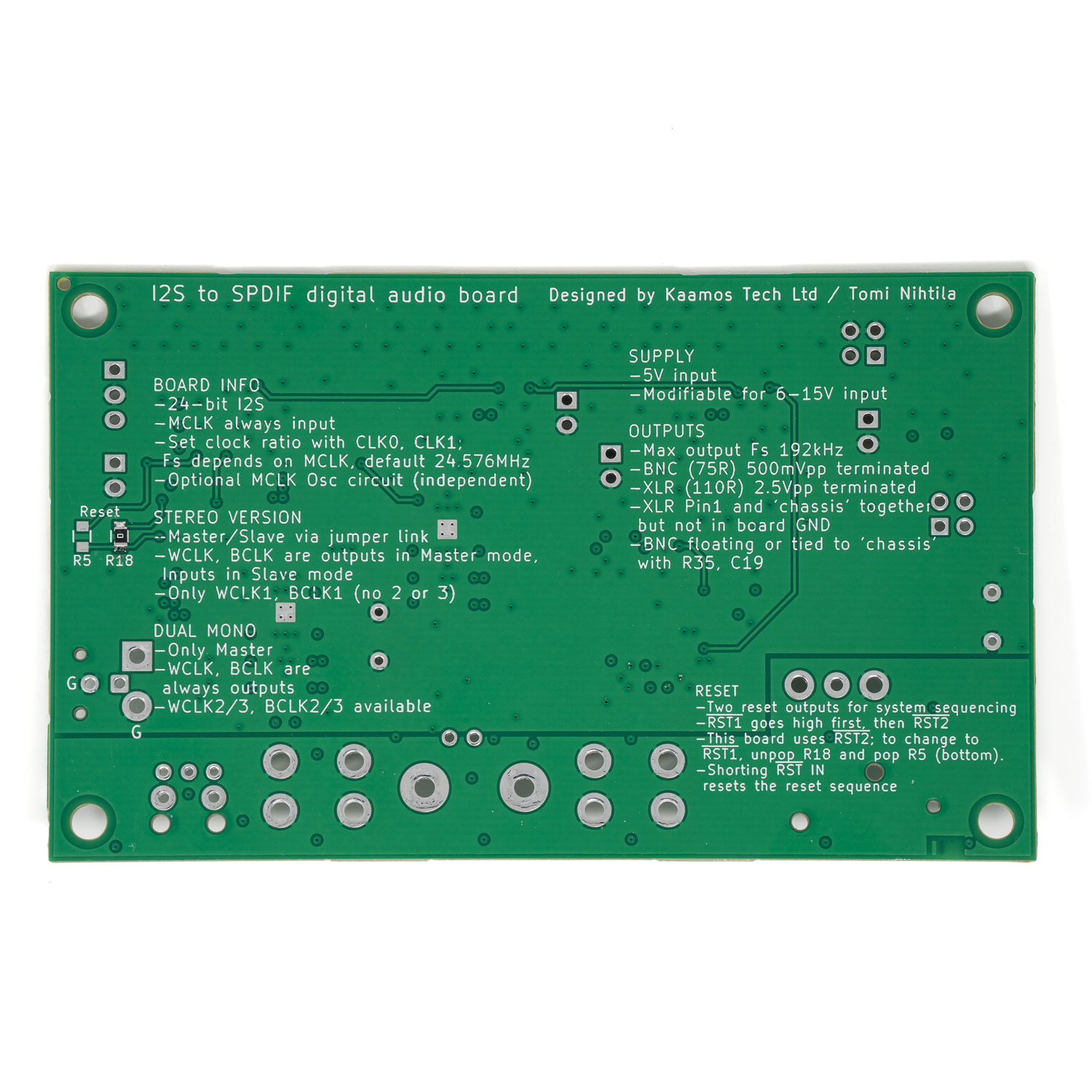
- Sample rate 48 kHz, 96 kHz, or 192 kHz; selected via jumper links
- Special Dual Mono version (I2S Master only) to work with 2x ADC AK5572 in Mono mode
- Optional oscillator circuit for Master Clock with three outputs
- DIT4192 S/PDIF transmitter, LT3042 LDO
Requires following supplies (indicated max current):
- 5V (40 mA)
Performance
Performance was verified by chaining I2S source + SPDIF TX + DAR 18 + W-DAC and the analog output performance was verified the same to I2S source + W-DAC.
Oscillator circuit selection
Most use cases don’t need onboard oscillator. If you already have a system with MCLK, you must the existing one for everything to be in sync. Therefore, “No oscillator circuit” is suitable option for most use cases.
If you do have existing MCLK but want to buffer and split it to use on several boards, select “Yes, with U.FL input”. This option gives you MCLK U.FL input and buffer that splits the clock into three U.FL outputs that can be used elsewhere (including SPDIF TX board).
If you do need/want onboard oscillator, there are two more options:
- “Yes, with standard 24.576MHz OSC” uses onboard Connor Winfield or similar oscillator. We have used this oscillator in our own tests and it is perfectly adequate to give you top measurable performance.
- “Yes, without source (use your own or buy CCHD)” gives you the buffer circuit but no oscillator so you can solder down your own oscillator – just check the footprint* is supported. Or, you can buy Crystek CCHD-957 oscillator from us (if we have it in stock).
The oscillator selection includes soldering it down. If you also buy Crystek CCHD oscillator, we will also solder it down.
*It is a dual footprint to support 7x5mm Connor Winfield oscillator or Crystek CCHD-957.
Note that one of the three MCLK outputs must be looped back to this board, there is no connection on the PCB.
Many options can cause confusion so please contact us if in doubt. However, as said, in most cases no oscillator or oscillator circuit is needed.
Reset circuit
There is an extra reset circuitry for advanced users. When the SPDIF TX board is powered up, two reset signals go up around 1s apart. SPDIF TX is being enabled with the latter signal. These can be used for other boards in the system. See SPDIF TX v2 guide.
Important information on order
- All SMD components are soldered down and the board is fully tested, connectors and headers are soldered if selected.
- Please ensure you have the skills to solder the remaining components and wires to connect the board in your system – and most of all understand what you are doing. Especially pay attention you have the correct power supplies and signal levels.
- Be careful with supply polarity and level, incorrect connections may damage the board and/or your power supply.
- If you need help prior to purchase, please contact us.
Order contents
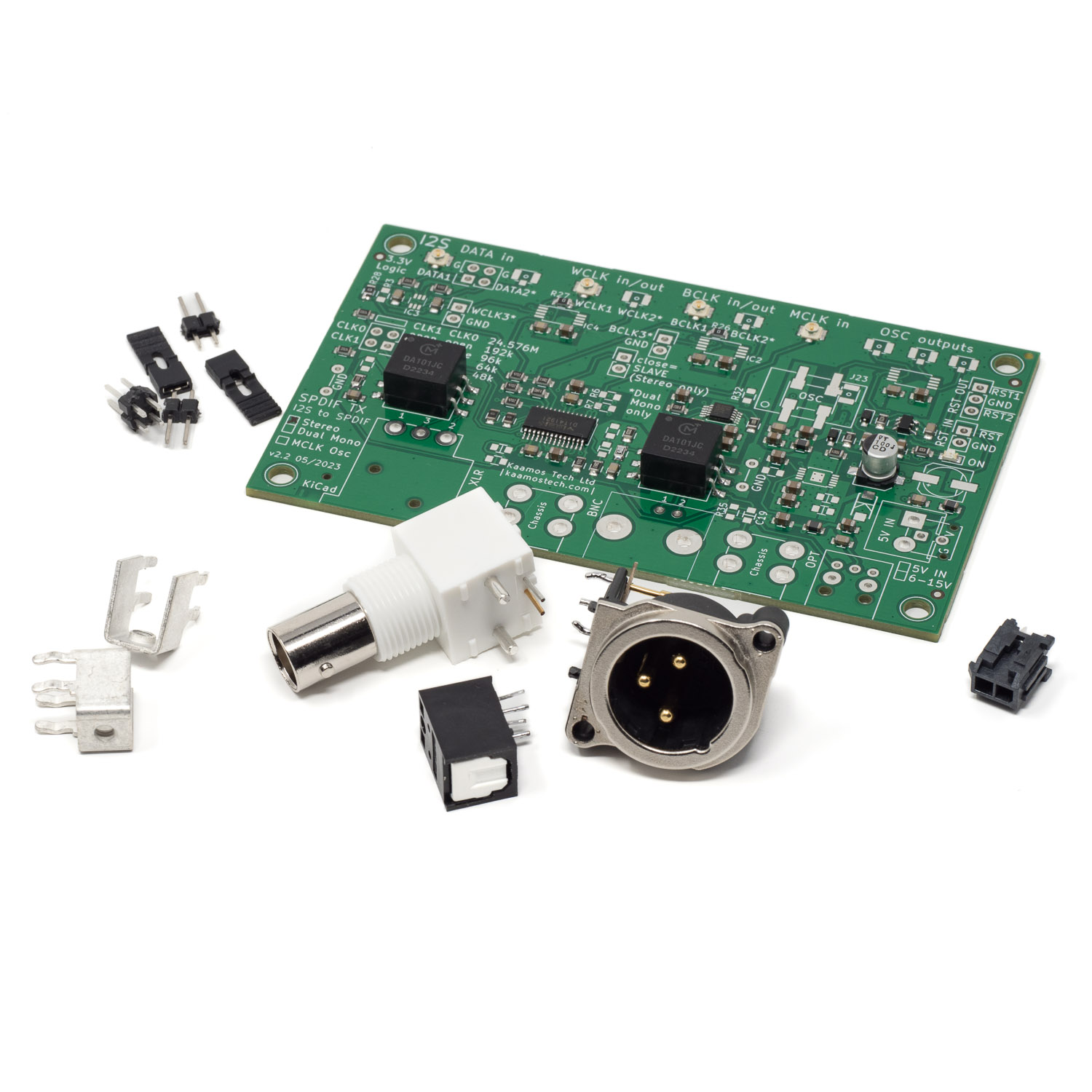
List of what is included in the order.
Stereo version:
- Fully tested board with all SMD components populated
- BNC connector
- Neutrik XLR male connector
- Optical Toslink transmitter
- 2x PCB to back panel mounting terminal
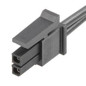
- 2-pin Molex power connector
- 2×2 male pinheader + two jumper links for sample rate selection
- 2x 1×2 male pinheaders for Master/Slave selection (+ jumper link) and optional reset input/output
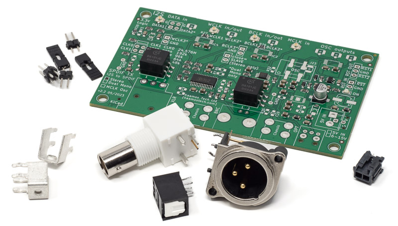
By default, connectors and headers are delivered unsoldered.
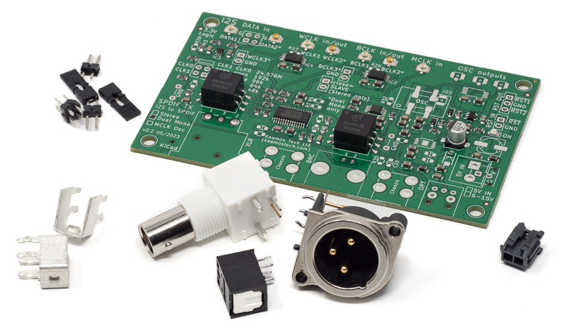
Dual Mono version:
- Fully tested board with all SMD components populated
- BNC connector
- Neutrik XLR male connector
- Optical Toslink transmitter
- 2x PCB to back panel mounting terminal
- 2-pin Molex power connector
- 2×2 male pinheader + two jumper links for sample rate selection
- 1×2 male pinheader for optional reset input/output
(image below has two 1×2 headers but only one is included)
More information
For more information on using the board, see SPDIF TX v2 guide. There is also a post on how to connect ADC AK5572 and SPDIF TX.
Files
- Schematics
- Component placement top (including board dimensions)
- Component placement bottom

