Following is additional information on using Kaamos W-DAC board. Please also see the product description. If something is still unclear, please contact us. We will try to update the information based on feedback.
Power supply
The board only requires 5V for digital VD supply. This should not exceed 5.5V. You can use 2-pin Molex Micro-Fit connector with compatible Kaamos power supply, or cut and use the cable connected to your own power supply. Or you can just solder the supply wires.
There is a placeholder to populate 5V regulator on the PCB and then use 6-15V supply input. However, this has not been implemented and is not provided as a board option when purchasing so you would need to do it yourself.
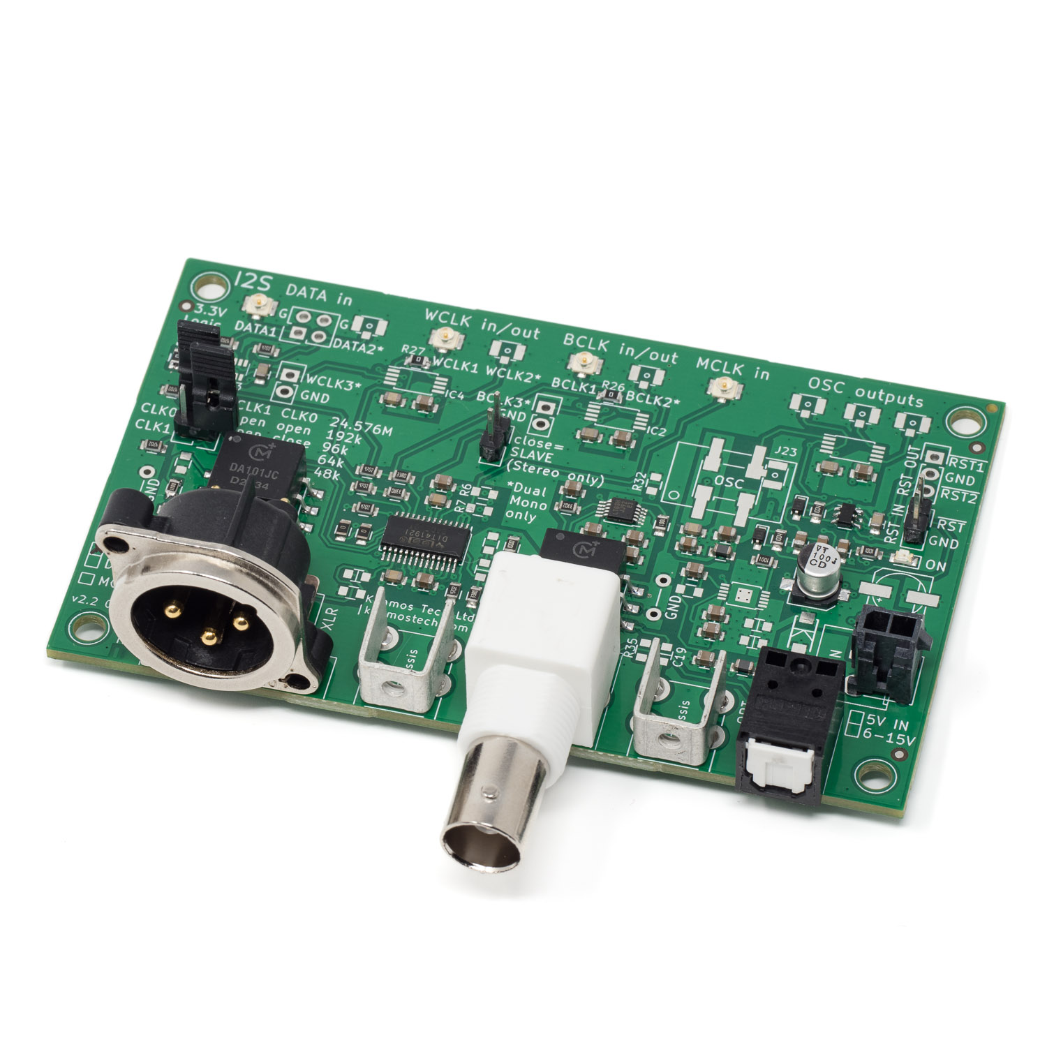
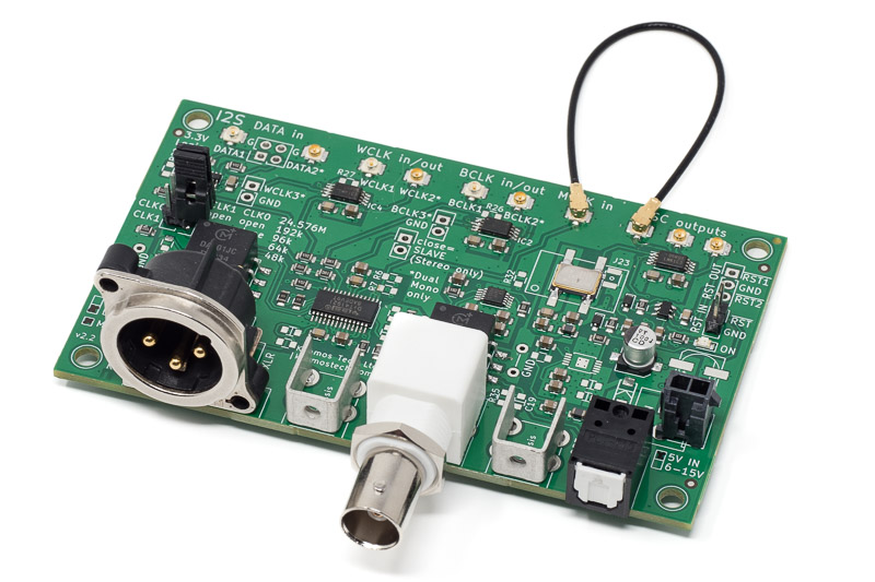
PCM/I2S signal input
SPDIF TX has a PCM digital serial input consisting of following four signals:
- MCLK – Master Clock input
- BCLK – Bit Clock
- WCLK – Word Clock (sometimes also referred as LRCK)
- DATA – Data input
BCLK and WCLK are inputs in Slave mode and outputs in Master mode. Maximum WCLK is 195 kHz and max MCLK 25 MHz.
Signal level is 3.3V and there is no termination. MCLK must be in sync with BCLK and WCLK when provided externally.
For information on using U.FL cables with headers, please see this post.
S/PDIF outputs
All three outputs are independent and can be used simultaneously. BNC output level is 0.5Vpp (75R terminated) and XLR output level is 2.5Vpp (110R terminated).
If you need an RCA output, a simple BNC-RCA-adapter can be used.

Channel configuration
Two variants of the board exist, and while the PCB is the same there are significant BOM differences. Dual Mono version has separate clock buffers to split BCLK and WCLK into two. Data is formed from two data inputs.
Stereo
This is the ‘normal’ version of the board. There are one BCLK, WCLK and DATA each. Master/Slave mode can be changed with jumper link; in Master mode BCLK and WCLK are outputs and in Slave mode they are inputs.
Dual Mono
Dual Mono version is meant to be used with two ADC AK5572 in Mono mode. It works only in Master mode. It splits all clocks into two with buffers and combines a stereo S/PDIF stream from two I2S data lines. By using the onboard oscillator circuit and adding a PSU, one can build a very high performance Dual Mono ADC to S/PDIF system.
As the buffers used have three outputs, there are optional third outputs for BCLK and WCLK.
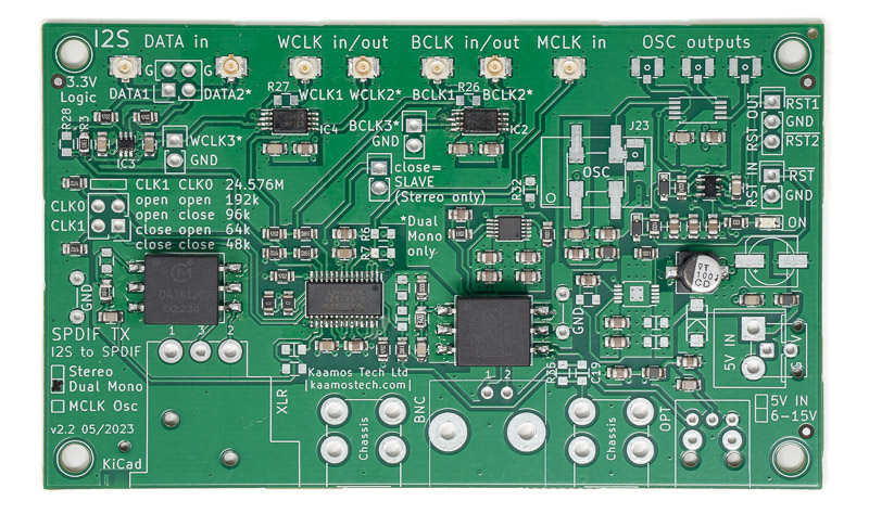
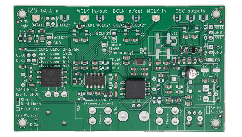
Sample rate selection
Sample rate is selected with CLK0 and CLK1 jumper links. This selects the ratio of the given MCLK and sample rate (WCLK). Usually MCLK is 24.576 MHz and the examples on silkscreen are given for that, e.g. close both links for 48 kHz sample rate.
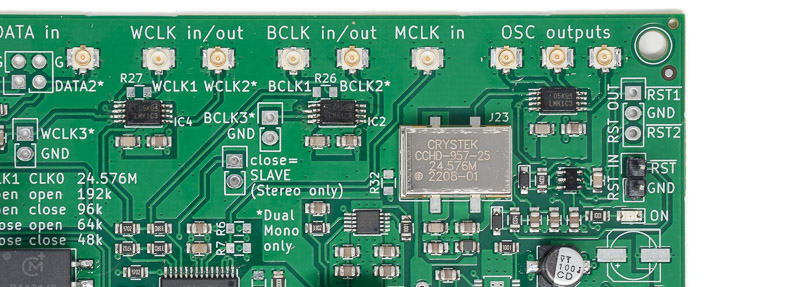
Optional oscillator circuit
There is a placeholder for oscillator, supporting a common 5x7mm footprint and a Crystek CCH-957 footprint, followed by a clock buffer with three outputs.
This can serve in two different situations:
- Use oscillator, use buffer, and provide MCLK for up to three boards
- Use buffer without oscillator; use U.FL input (J23) instead to split external MCLK for up to three devices
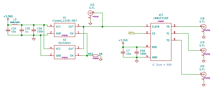
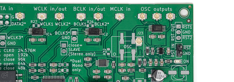
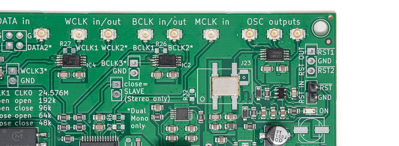
Note that there is no internal loopback to this board from the buffer so you need an external loopback, shown below, when using the oscillator circuit to provide MCLK to SPDIF TX.
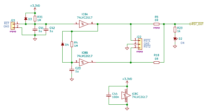
Reset circuit
There is a reset circuit with two outputs onboard. With default components there is around 1s delay for nRST1 signal to go high, and another 1s delay before nRST2 goes high. The SPDIF TX board itself uses nRST2 to power up, although this can be changed with 0R resistors.
You can also control the first reset step with external logic signal.
This has been implemented because some boards require power-up before applying clocks. For example, AK5572 (ADC used in AK5572 board) datasheet recommends (page 31) applying MCLK after configuration when synchronising multiple AK5572s – in which case this may be beneficial to do when using 2x ADC AK5572 Dual Mono with SPDIF TX, as explained below. Most likely it will not be an issue not to use the reset but this way perfect clock synchronisation should be guaranteed.
If you don’t need the reset circuit, just ignore it.
If you need faster SPDIF TX startup than the default almost 2 seconds, you can change the RC constants of the reset circuit, or just short the 1M resistors R31 and R4 for instant power-up.
More information
See SPDIF TX v2 product page and a post on how to connect ADC AK5572 and SPDIF TX.