One Four All – Low-Noise Audio PSU
- 5V input via USB-C or wires:
- At least 2A USB supply recommended, heavy loading requires 3A.
- Use USB power bank for fully isolated power.
- Generates the following supplies from a single 5V input:
- VD – 5V digital, up to 400mA.
- VA – 6V analog reference supply, up to 150mA.
- VP/VN (+/-13.3V analog amplifier/opamp supply), up to 250mA per supply.
- Molex Micro-Fit power output connectors to power multiple Kaamos boards (subject to current limits) with simple connections:
- 2-pin Molex for digital-only boards.
- 6-pin Molex for mixed-signal boards.
- All output connectors are in parallel so total current per supply must be within the limits.
- Extensive protection features for increased reliability and robustness:
- Power-up sequencing to decrease inrush current.
- Input reverse polarity protection.
- Input over-voltage protection and under-voltage shutdown.
- Current limit and under-voltage shutdown on each output channel; if one shuts down, all shut down.
- Soft power button to toggle the PSU between standby and active states.
- Hard power switch to fully turn off power (recommended when not in use).
- Mute output to quickly mute DACs in case of output failure.
- PCB is 107×52.5mm (slightly larger than v1.5).
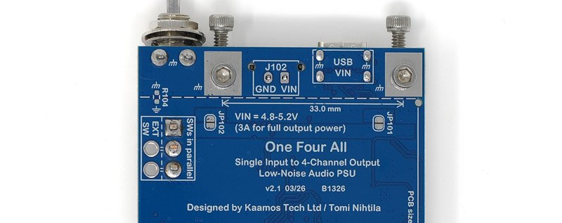
Power input
Input is nominal 5V (4.8-5.2V). Due to voltage drop in the cable and input circuits, a slightly elevated voltage of 5.1-5.2V eases thermal stress of the PSU with heavier loads. We have used official Raspberry Pi 3A (27W model) and 5A (45W model) supplies in our tests and they have worked really well.
Under heavier load the USB cable also matters. We recommend a short or thick cable; low resistance is key.
See the board guide for examples of current consumption.
Notes:
- VIN connector / wiring is in parallel with USB-connector – do not use both simultaneously.
- USB is power only (type C USB2). There are no data or handshaking, only 5.1k resistors on CC pins.
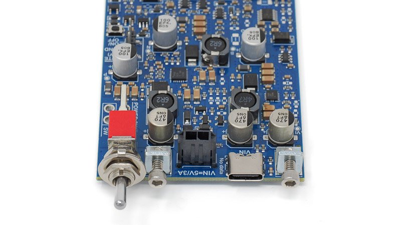
Hard power switch
Toggle power switch (new in v2) completely turns off power which is recommended in DIY electronics when not used. If the board is mounted on a panel, the switch is accessible next to the USB power input.
There is an ‘EXT SW’ placeholder next to the onboard switch which allows wiring an external power switch, e.g. if another style or location of switch is preferred. This is in parallel with the onboard switch so the onboard switch must be off. Any external switch must be rated for 3A DC or higher.
Soft power button
Soft ON/OFF button (new in v2, v1.5 had separate ON and OFF headers) toggles the PSU between ON and OFF (standby). Besides the onboard button, an external button can be wired between the ‘GND’ and ‘ON/OFF’ pins of the header. It is only for logic signal and can be a small signal switch with thin wires.
Due to limitations of the already complex hardware state-machine, when toggling from OFF to ON and keeping the button depressed for longer than around 1 second, the PSU toggles back from ON to OFF.
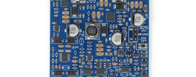
Soft ON/OFF button on the right edge, or external button between ‘ON/OFF’ and ‘GND’ on header.
Power-up
Upon power-up, the PSU turns ON automatically (this can be changed, see below). All output channels (5V, 6V, +/13V) are turned on in a sequence to minimise start-up current spike. Successful ON-state is signalled by the ON LED. MUTE output is low.
OVL/FAULT LED signals a state where the PSU tries to be ON but there is a fault in the outputs. It is normal it to blink when transitioning between OFF and ON. This state should never be longer than a blink since any fault should turn off the outputs and go to OFF state.
If the PSU fails to power-up (not staying ON), please see capacitance options below or startup troubleshooting in the OFA Guide.
If you connect a high capacitance load when the PSU is ON, it is normal it turns OFF because the current spike triggers over-current protection. When the PSU is turning ON, the over-current protection is temporarily disabled so it can charge load capacitances.
Input capacitance options
New in v2 are options for input capacitance. By default, the PSU has 470uF input capacitor. This is already a high capacitance in a USB device but it has proven to be beneficial to help the PSU start up in different scenarios.
However, 470uF is not enough for a robust start-up in some cases. For example, if the PSU is powered by Raspberry Pi, this can lead to an oscillating state where the PSU tries to start up, but RPi cuts off the power due to high start-up current, and this keeps repeating. Adding more input capacitance helps. Therefore, there are two additional 470uF capacitors that are disconnected by default but can be added via shorting links on the bottom side. In our tests adding one more was enough for Raspberry Pi 5.
Short JP101 and/or JP102 to add more input capacitance, 470uF each.
Changing default power-up state
By default, the PSU turns ON when power is turned on. This can be changed with a shorting link on the bottom side. By shorting the link, the board defaults to OFF after power-up. Engaging the soft power button (or header) turns the PSU ON.
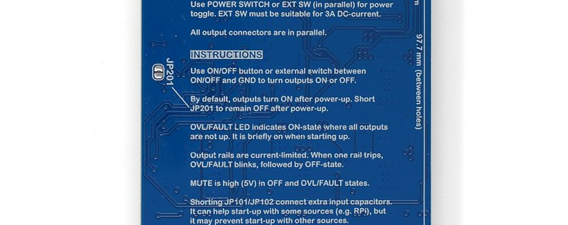
Short JP201 to remain OFF after power-up.
Mute output
Active-high (around 5V through 1k resistor) mute output can be used to signal standby-state to external circuits. It is high when the PSU is OFF, and low when it is ON. Alternatively, this could be used for an external standby LED.
Using with non-Kaamos modules
If you want to use the PSU with boards that don’t have Molex power connectors, the best option is to get a power cable (6-pin / 2-pin) and cut the connector off at one end, and solder the wires to your circuit.
Important information on order
- All required components are soldered down and the board is fully tested.
- Please ensure you have the skills to solder the remaining components and wires to connect the board in your system – and most of all understand what you are doing.
- If you need help prior to purchase, please contact us.
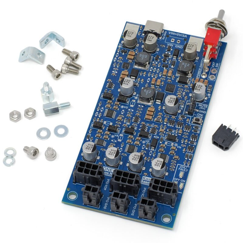
Order contents
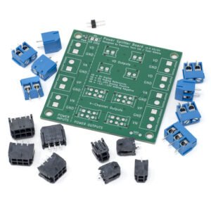
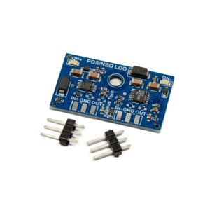
The board is delivered with following parts included, shown in the photo below:
- Fully tested board with all components populated.
- VIN Molex connector.
- PCB panel mount kit for USB-end:
- 2pcs small L-brackets.
- 4pcs 4-40 1/4″ screws (hex head, likely imperial but around 2.5mm).
- PCB bottom mount kit:
- 2pcs 6mm standoff.
- 2pcs M3 bolt (2.5mm hex head).
- 2pcs M3 nut.
- 2pcs M3 flat washer.
- 2pcs M3 spring washer.
More information
See the One Four All Guide for more information on the following topics:
- Input voltage range and impact of wiring resistance.
- Number of boards OFA can supply.
- Soft-start and soft-stop.
- OFA startup problems.
Files
We do not guarantee the files are 100% match with the board. Especially when it comes to mechanical design based on the 3D-model, please verify any dimensions on the actual board since the model relies on 3rd party component models we have not verified.
- Schematics may be released later on
- Component placement and board dimensions
- 3D-model (.step, 75MB)
- Older version v1.5 product page in PDF