Clock Buffer 1-4 – High-Performance Quad 1:4 Clock Fanout Buffer
- Split and buffer PCM/I2S signals – or any clock up to 200 MHz.
- EN-input to enable/disable clock outputs.
- Compact 85 mm x 30 mm 4-layer PCB.
- LMK1C110x clock buffers.
- Optional oscillator circuit to provide Master Clock.
Requires following supplies:
- 5V (4.5-6.0V), 20-100mA in normal use cases.
- Current depends on clock frequency, number of outputs used, and output capacitance and termination.
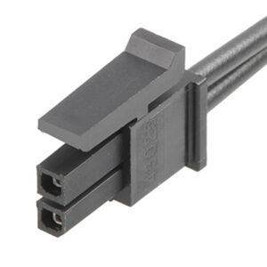
- Supply provided via 2-pin Molex Micro-Fit.
- If using a non-Kaamos power supply, we recommend purchasing a 2-pin Molex power cable, cutting one connector off, and soldering the wires to your power supply.
This product replaces Clock Buffer 1-3. It is practically identical but has four outputs per channel instead of three.
When do you need a Clock Buffer 1-4?
Typical use case is when connecting several DACs, ADCs or other digital audio boards to a DSP that has one set of clocks (Bit Clock BCLK, Word Clock WCLK, and possibly Master Clock MCLK) available. Simply splitting the clock lines is not a good idea due to multiple reflection paths, decreasing reliability or stopping the interconnected boards from working altogether. A proper way to split the clocks is to use a clock fanout buffer with multiple outputs – like the Clock Buffer 1-4.
If the host board such as a DSP has enough several independent clock outputs already, external buffer is not needed.
Pay attention to clock directions. Typically DSPs and USB-modules are I2S Masters (clocks are outputs), in which case the converters and boards connected must be Slaves. To connect two Masters or two Slaves, a sample rate converter is required.

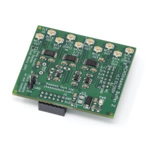
Four channels
The board has four output ‘channels’. These are named MCLK (Master Clock), BCLK (Bit Clock), WCLK (Word Clock), and DATA for convenience since the intended application is digital audio. However, all channels are independent and identical, and can be used for any digital signal with 3.3V level. The board has been tested up to a few tens of MHz (digital audio clocks are typically less than 50MHz) but the buffer IC’s specs are up to 250MHz. Please see LMK1C110x datasheet for details.
Clock inputs
Each channel has a UFL-connector for the input signal. There is also a 2-pin SMD-header placeholder for each input; the headers are included with the board but not soldered down (unless solder down option is selected). There are also placeholders for termination components; see schematics and component placement if these are required in your application.
Clock outputs
Each channel has four outputs provided via UFL-connectors, and all outputs are identical. The output impedance of each output is 50 ohms.
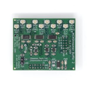
Outputs can be disabled by shorting OUTPUTS nEN header. This disables all outputs of all channels. Alternatively, this can be driven by an external logic signal (low disables outputs).
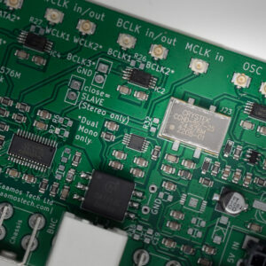
Optional oscillator
There is an optional oscillator placeholder. This can be used as a Master Clock for the system, for example. OSC OUT can be connected directly to a Slave device or to one of the four clock inputs to split the OSC into four to connect to multiple Slave devices.
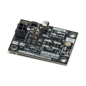
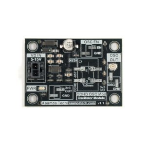
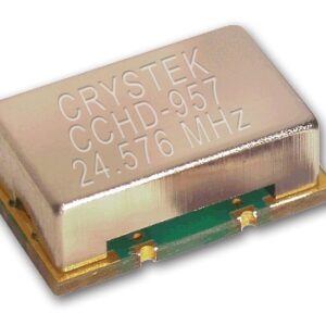
Connor Winfield CWX813 oscillator is good enough to hit the headline audio spec figures in our DAC and ADC tests. However, Crystek CCHD-957 is offered as a truly high-performance clock oscillator. If you do want the highest clock performance, consider a separate clock module like CCHD OSC Module which has its own low-noise regulator for the oscillator.

OSC OUT connected to MCLK IN to split the oscillator into four outputs.
Important information on order
- All components (except optional 2-pin input headers) are soldered down and the board is tested.
- Please ensure you have the skills to connect the board in your system – and most of all understand what you are doing. Especially pay attention you have the correct power supplies and signal levels – incorrect connections may damage the board and/or your power supply.
- If you need help prior to purchase, please contact us.
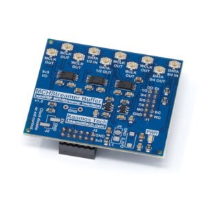
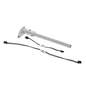
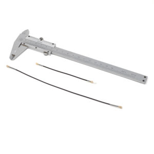
Order contents
See contents in the photo below:
- Assembled and tested board.
- Optional oscillator also soldered if selected.
- 5pcs 1×2 male SMD-pinheader.
- 1pc jumper link.
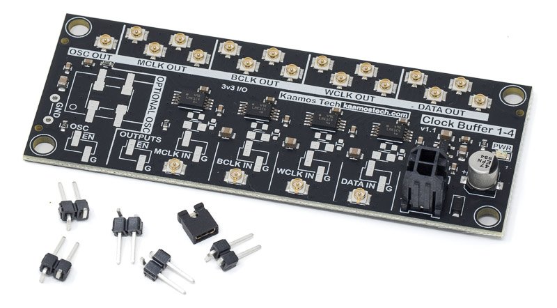
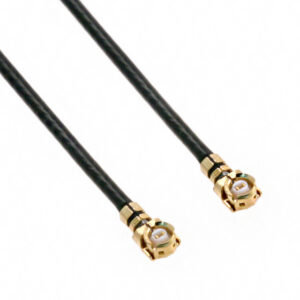
Please purchase power cable and UFL-cables separately.
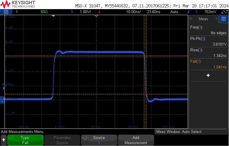
More information
For measurement results and version history, see the tab above.
See the video below why a clock buffer is a great idea.
Files
- Schematics
- Component placement (including board dimensions)