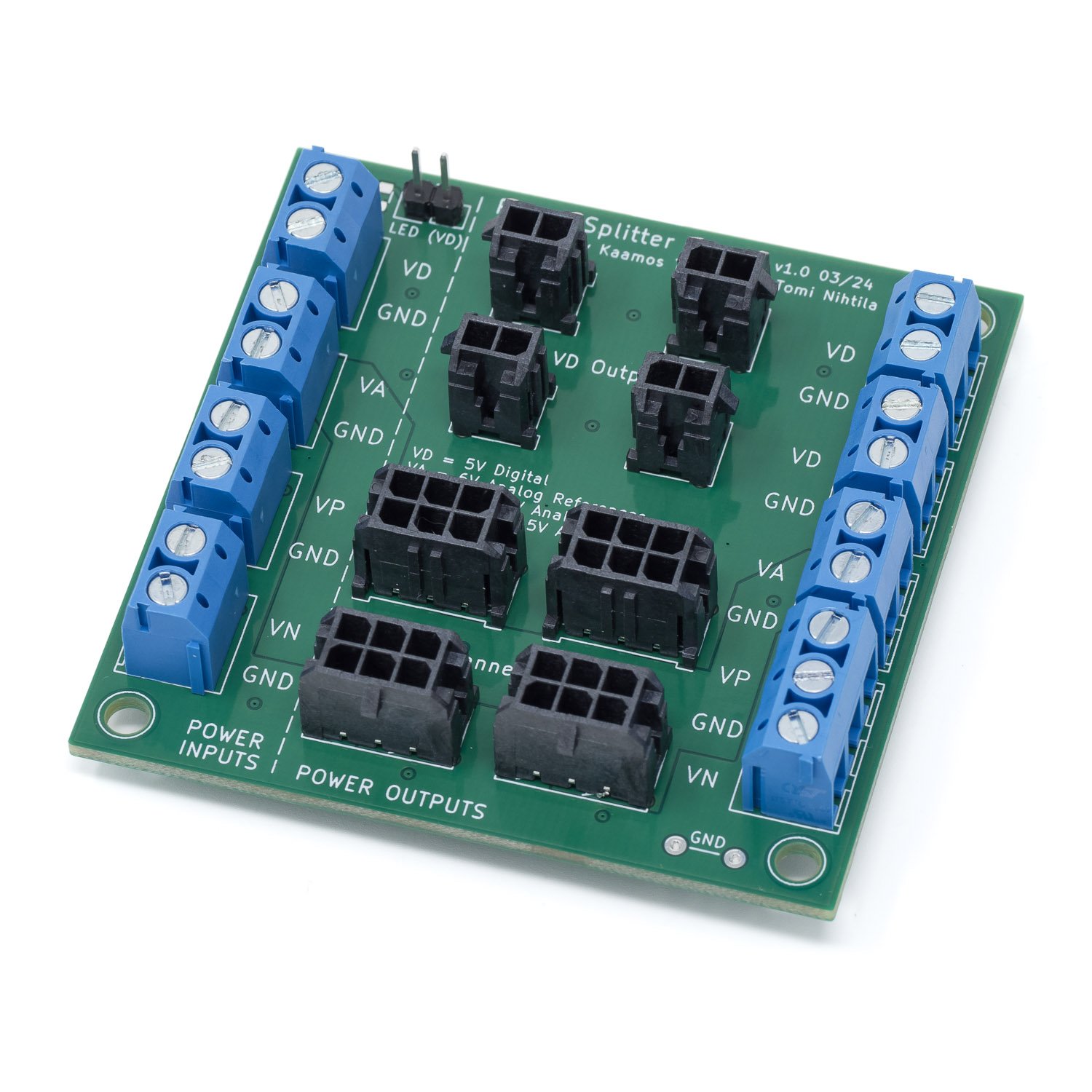
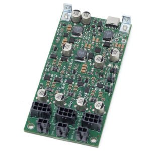
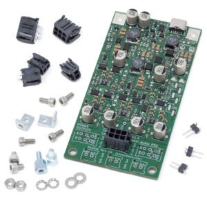
The board is a simple passive power splitter board that allows the use of Molex Micro-Fit power cables with all power supplies.
Generic use
Power Splitter is meant to be used with generic non-Kaamos power supplies. Connect the following regulated supplies to the left-hand side POWER INPUTS of the PCB:
- VD: 5V
- VA: 6V
- VP: 12…15V
- VN: -12…-15V
- GND: all ground terminals on the PCB are connected together, connect as many as available.
If only 2-pole Molex outputs (“VD Outputs”) are used for digital-only boards, only VD input supply is required. Moreover, some converter boards do not need VA supply but can take it from the VP. See individual board instructions.
Connect boards to be powered to the POWER OUTPUTS connectors or terminals. There is also a power LED connector, connected to VD supply via a 1k resistor.

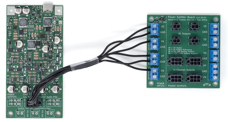
In the illustration-only photo below, an old nihtila.com PSU baseboard is used to connect regulator outputs to a Power Splitter which then connects to DAR 18 and W-DAC. Use as short wires as possible from the PSU to the Power Splitter to minimise common impedance.

Use with One Four All PSU
Important note if thinking of using the Power Splitter Board to expand One Four All PSU output connectors. Do NOT connect One Four All 6-pin output Molex to one of the 6-pin Molexes on the Power Splitter Board. Molex Micro-Fit cables are not cross-connected but the two ends of the cable assembly are mirrored. Therefore, the connector PCB pinout is also mirrored between power input and power output! See below the pinout of OFA power supply (output) and W-DAC (input).


One Four All output connectors should be enough but if you wish to split them with Power Splitter, get one 6-pin power cable, cut off the connector, and connect the cable to the screw terminals as shown below. Use as short cable as possible to minimise common impedance.
