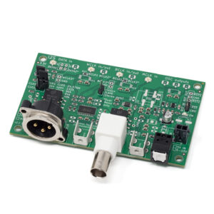
SPDIF TX v3 – I2S to S/PDIF Converter
PCM I2S to S/PDIF digital audio converter with I2S serial audio input and RCA/BNC, Toslink, and XLR outputs.
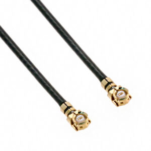
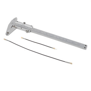
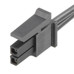
- I2S input via U.FL-connectors.
- I2S Master or Slave.
- Three S/PDIF outputs: RCA/BNC (choose one), Toslink, and XLR (AES/EBU).
- All outputs galvanically isolated.
- All outputs can be used simultaneously.
- If you want BNC with RCA-option, see BNC-RCA adapter.
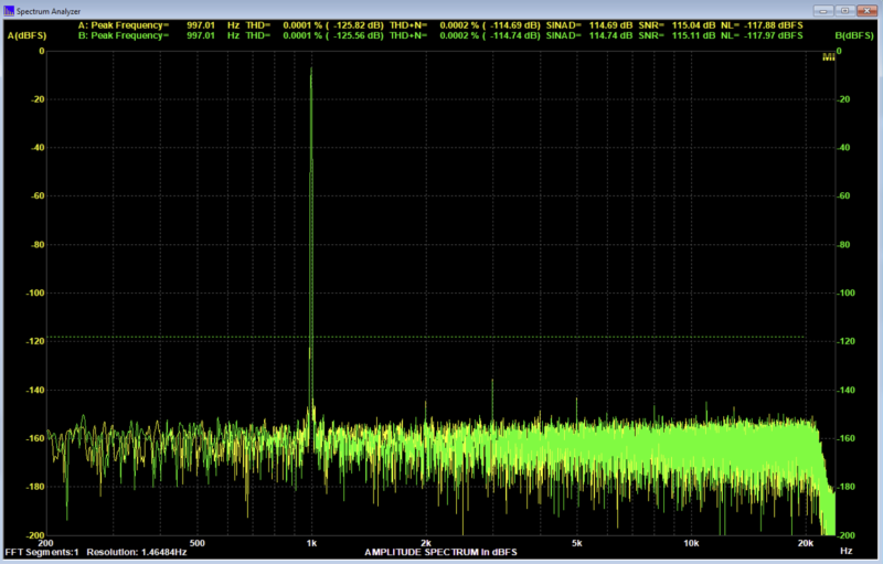
- Sample rate 48 kHz, 96 kHz, or 192 kHz; selected via jumper links (or 3.3V logic signals).
- Sample rates depend on the Master Clock, above is with 24.576MHz MCLK.
- Optional oscillator circuit for Master Clock with three outputs.
- DIT4192 S/PDIF transmitter.
Requires following supplies (indicated max current):
- Wide input voltage range: 4.9-15.5V (40 mA).
- Supply provided via 2-pin Molex Micro-Fit.
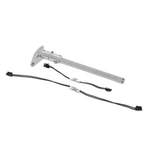
- If using a non-Kaamos power supply, we recommend purchasing a 2-pin Molex power cable, cutting one connector off, and soldering the wires to your power supply.
Master/Slave selection
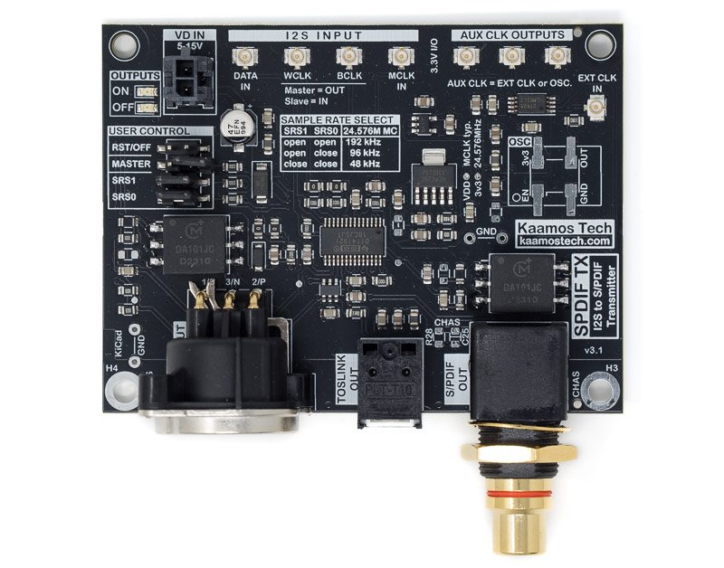
Master or Slave operation is selected with a jumper link or equivalent 3.3V logic signal (open/low is Slave). In Slave mode BCLK and WCLK are clock inputs, in Master mode they are outputs. MCLK and DATA are always inputs.
Sample rate selection
Sample rate is selected with two jumper links or equivalent 3.3V logic signals (open jumper link is low). The clock table is printed on the silkscreen for 24.576MHz MCLK; the selection adjusts the MCLK/WCLK ratio and therefore depends on the MCLK. For example, the 192kHz selection applies for 24.576MHz MCLK but with 12.288MHz it would be 96kHz and with 11.2896MHz it would be 88.2kHz.
It is important to note that SPDIF TX does not automatically lock to any sample rate and MCLK. If the source changes the sample rate, e.g. from 48kHz to 96kHz, it works if the MCLK changes accordingly so that the MCLK/WCLK remains the same. If the ratio changes, it needs to be re-configured.
Reset/off state
Closing RST/OFF jumper link (or applying logic low) puts the board in off-state, and red OUTPUT OFF led is lit.
Clock buffer and oscillator circuit
The board has an independent clock splitter and buffer circuit (similar to Clock Buffer 1-4) with one U.FL-input and three outputs. It can be used to split Master Clock, for example.
If the system does not have Master Clock, an optional oscillator can be populated onboard and its output split into three. You can use and solder down your own oscillator (7x5mm and Crystek CCHD-957 footprints), or you can choose one of the two options:
- “Yes, CWX813 24.576MHz OSC” comes with a Connor Winfield CWX813 oscillator soldered down. We have used this oscillator in our own tests and it is good enough to give you top measurable performance.
- “Yes, Crystek CCHD-957 (sold separately)”; this option does not include the oscillator but notes us to solder down a very high quality Crystek CCHD-957 oscillator you must purchase separately.
Most use cases don’t need an onboard oscillator. If you already have a system with MCLK, you must use the existing one for everything to be in sync. Therefore, “No oscillator” is suitable option for most use cases.
Do not use both the oscillator and EXT CLK IN simultaneously. The input is either an external clock on U.FL or the oscillator, not both.
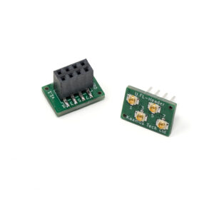
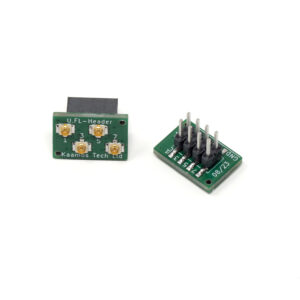
Note that one of the three MCLK outputs must be looped back to this board (shown below) if used for MCLK, there is no connection on the PCB.
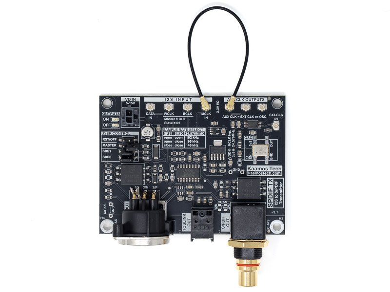
MCLK loopback when using onboard oscillator for MCLK (U.FL cable not included).
Important information on order
- The board is fully assembled (including all connectors) and tested.
- Please ensure you have the skills to connect the board in your system – and most of all understand what you are doing. Especially pay attention you have the correct power supplies and signal levels – incorrect connections may damage the board and/or your power supply.
- If you need help prior to purchase, please contact us.
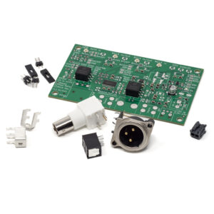
Order contents
List of what is included in the order.
- Fully assembled and tested board. This includes all connectors, choose S/PDIF OUT to be RCA or BNC.
- 3pcs jumper link with handle for sample rate and Master/Slave selection.
Files
- Schematics
- Component placement top (including board dimensions)