LT30xx LDO Module – High-Performance Voltage Regulator Modules
Voltage regulator module for DIY-builds or modifications.
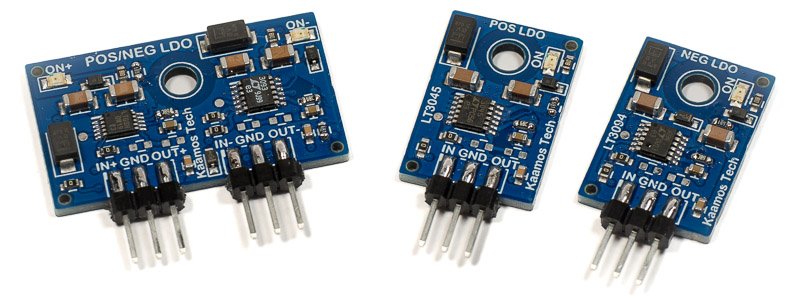
- Three models, all using very high-performance low-noise LT30xx regulators:
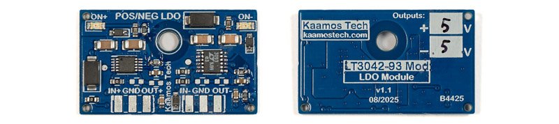
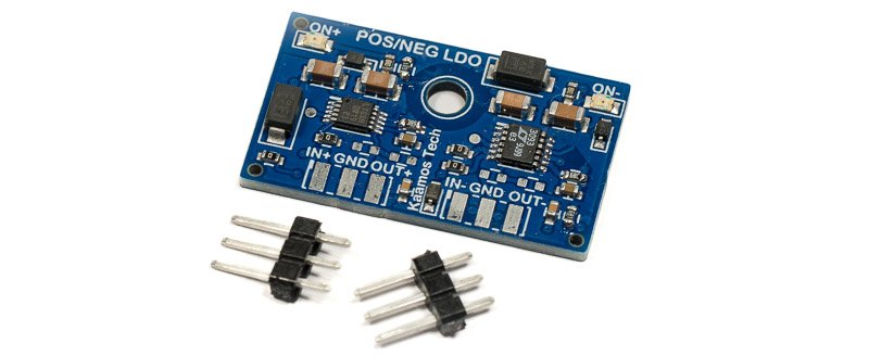
- LT3042-93 Module: LT3042 + LT3093 for positive and negative output voltages at 200mA each.
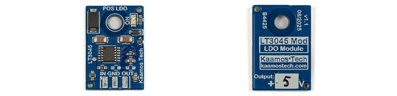
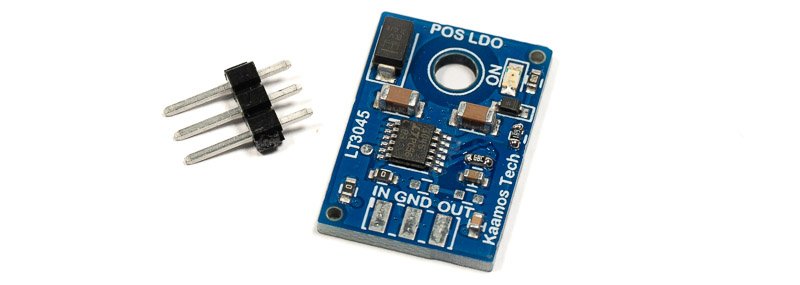
- LT3045 Module: Positive output voltage at 500mA.
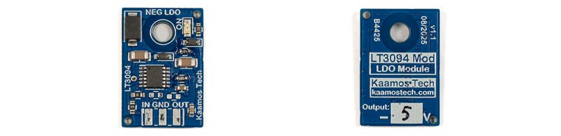
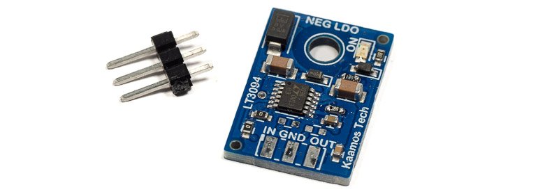
- LT3094 Module: Negative output voltage at 500mA.
- Customisable output voltage.
- Very compact form factor suitable for product modifications.
- LT3042-93 Module: 32mm x 19mm.
- LT3045 and LT3094 Module: 15mm x 22mm.
Input voltage
Maximum input voltage is 20V. Exceeding it will damage the board.
Power dissipation
Maximum output current depends on the module. However, power dissipation ([Vout-Vin] * current) may become more significant.
- 1W dissipation in the LT3045 and LT3094 modules lead to around 100C temperature at room temperature. Therefore, the dissipation should be lower.
- LT3042-93 module gets to around 100C when both sides are dissipating 0.65W so these should be lower.
- Temperature can be lowered slightly by attaching the board to a heatsink. Isolation pad shall be used in case the solder mask scuffs and exposes vias.
Headers
Through-hole headers can be soldered horizontally for easier integration with other circuits. Alternatively, wires can be soldered to the pads.
Note that pinouts of the LT3094 module and negative side of the LT3042-93 module do not follow 79xx regulators. They are all IN-GND-OUT.
Wiring and external capacitors
The modules are designed to be used close to the application circuit. If they are wired by long wires (more than 5-10cm), it may be beneficial to solder an electrolytic capacitor (e.g. 47uF or 100uF) at the header between IN and GND – just in case. Long wires and onboard ceramic capacitors can potentially cause oscillations. That being said, the modules have been tested with 50cm cables without any signs of oscillations.
Power LED
Green LED is lit when the module is powered up.
More photos
LT3042-93:
LT3045:
LT3094:
Important information on order
- All components (except headers) are soldered down and the board is tested.
- Please ensure you have the skills to connect the board in your system – and most of all understand what you are doing. Especially pay attention you have the correct power supplies – incorrect connections may damage the board and/or your power supply.
- If you need help prior to purchase, please contact us.
Order contents
One purchased item is one module.
Modules come assembled and tested, with optional header(s) which can be soldered if selected.
LT3042-93:
LT3045:
LT3094:
Files
We do not guarantee the files are 100% match with the board. Especially when it comes to mechanical design based on the 3D-model, please verify any dimensions on an actual board since the model relies on 3rd party models we have not verified.
LT3042-93
- Schematics
- Component placement (including board dimensions)
- 3D-model (.step)
LT3045
- Schematics
- Component placement (including board dimensions)
- 3D-model (.step)
LT3094
- Schematics
- Component placement (including board dimensions)
- 3D-model (.step)