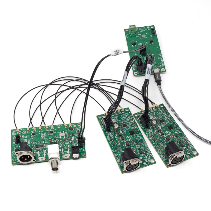
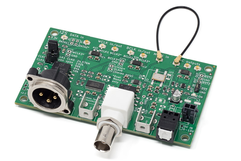
It is easy to add S/PDIF outputs to ADC AK5572 by using SPDIF TX.
Power supplies
SPDIF TX only needs 5V VD supply, while the ADC requires three or four supplies (see ADC AK5572 guide for more details). You can use your own power supply and solder wires or modify Molex cables for your needs, or you can use upcoming Kaamos power supply with easy power connections (the one in the photo is One Four All).
Stereo vs. Dual Mono
There are two main options to build this systems:
- Stereo ADC AK5572 + Stereo SPDIF TX
- 2x Mono ADC AK5572 + Dual Mono SPDIF TX
Stereo ADC AK5572 + Stereo SPDIF TX
All four I2S signals (MCLK, BCLK, WCLK, DATA) between the boards are easy to connect with U.FL cables. Just pick a suitable length.
The system needs MCLK source, for example optional oscillator circuit on SPDIF TX.
There are two options in terms of I2S Master/Slave choice:
- SPDIF TX Master, ADC AK5572 Slave
- ADC AK5572 Master, SPDIF TX Slave
It does not matter which way to use. In each case both boards need the same MCLK and it’s just a matter of which one generates MCLK and WCLK. In terms of configuration, it is easier to configure sample rate in SPDIF TX and therefore use it as Master and leave ADC to default Slave configuration.
2x Mono ADC AK5572 + Dual Mono SPDIF TX
The photo above shows this use case (except one MCLK cable is missing, see below). SPDIF TX board is I2S Master and also contains MCLK source. Therefore, ADCs are I2S Slaves and don’t need any configuration, just select suitable sample rate with SPDIF TX jumper links and the ADCs adapt to this.
Strictly following AK5572EN ADC IC datasheet, a well defined reset sequence should be followed. It has been discussed in SPDIF TX v2 guide. In this case, we would connect RST1 signal from SPDIF TX to both ADCs, and this would cause the ADCs to be powered up first, and then clocks applied. However, in our own measurements we did not see any difference in phase behaviour between the two ADCs, whether the reset was used or not.
MCLK source
All boards need MCLK from the same clock source. That is where the optional SPDIF TX oscillator circuit becomes handy. It has three MCLK outputs and can therefore support the Dual Mono use case. Each of the three boards need MCLK.


More information
Please read following to fully understand the functionality of the boards:
