Following is additional information on using Kaamos W-DAC board. Please also see the product description. If something is still unclear, please contact us. We will try to update the information based on feedback.
Power supply
The DAC board requires 5V for digital (VD), 6V for analog references (VA), and +/-15V (VP/VN) for output stage. 5V should be 5V (max 5.5V) but +/-15V can be lower, for example +/-12V works fine. If you don’t have 6V references supply, you can solder 2x ferrites or 0R resistors to take the reference supply from +15V. You can also just connect VP (+15V) to VA (6V) outside the board; however be careful if using other Kaamos boards in the system as VP-VA connection may not be allowed in all boards.
See current consumption per supply on product page.
If you use a Kaamos power supply, all four supplies are provided in one 6-pin Molex Micro-Fit connector. If not, you can solder your own power supply wires in the Molex footprint or order a power cable, cut one end and connect it in your power supply.
PWR led indicates power is on.
PCM/I2S signal inputs
W-DAC has PCM digital serial input consisting of following four signals:
- MCLK – Master Clock
- BCLK – Bit Clock
- WCLK – Word Clock (sometimes also referred as LRCK)
- DATA
MCLK must be in sync with BCLK and WCLK.
All these are inputs and provided with U.FL connectors. Signal level is 3.3V and there is no termination. The same connectors are used in DSD mode; see below.
For information on using U.FL cables with headers, please see this post.
Other signals
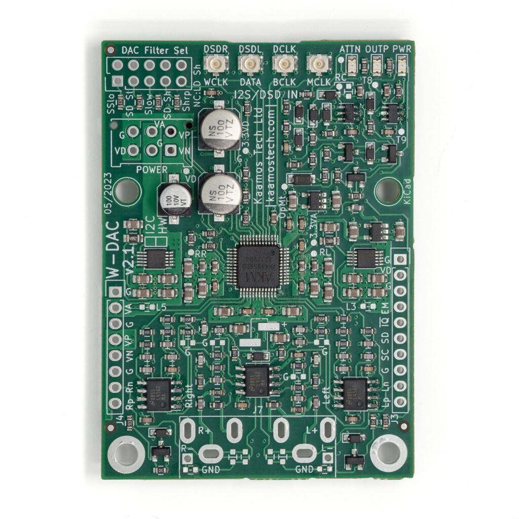
Signal names on silkscreen around power supply connector and edge headers:
- G = ground
- VD = 5V digital supply
- VA = 6V analog reference supply (can be taken from VP if not available)
- VP = +12…15V output stage supply
- VN = -12…15V output stage supply
- EM = EMUTE, external mute input, mute on when signal high; it is low when not connected
- SD = SDA, I2C data (I2C variant only)
- SC = SCL, I2C clock (I2C variant only)
- nIQ = IRQ from TCA9554 (I2C variant only), not used unless you connect your own inputs to TCA9554
- Rp/Rn, Lp/Ln = Right/Left pos/neg signals used for connecting XLR addon
Filter selection
Most DAC and ADC ICs offer selectable digital filters to fine-tune the response and sonic features. The impact of these filters on sound quality is minimal and not everyone can hear the difference. Feel free to try. The default option by the chip manufacturer is Sharp. A bit more on digital filters can be found on nihtila.com posts about PCM1794A filters and Audiolab M-DAC filters.
In HW variant filter selection is done by “DAC Filter Sel” jumper link or you can use a rotary switch to add the filter selection on the front panel. In I2C variant the selection must be done via register.
Mute
W-DAC has automatic mute circuit that hard-mutes the output if supplies are not up.
In addition, there is an external input (EMUTE) to this mute circuit that mutes the output when the signal is high (3.3V). When unconnected, it remains low.
OUTP led indicates mute is off (output on).
XLR output
There are two options to get balanced XLR output.
W-Output XLR addon
XLR output addon can be purchased separately. It has a completely independent output stage so RCA and XLR can be used simultaneously. Riser headers that place the addon on correct height and also provide power and signal are provided with the addon purchase.
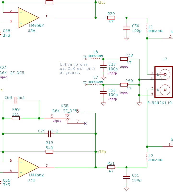
‘Pseudo-differential’ XLR output
It is possible to take XLR output from the W-DAC without the addon or any external circuit if you are fine with non-symmetric signal. This signal is differential and balanced but negative signal is ‘zero’ (ground potential) instead of inverted signal as commonly with balanced interconnection. In fact, pseudo-differential is incorrect term as the signal is differential and balanced this way but we use the term because it is widely known.
To do this, do not solder the dual RCA connector but solder the components under it to provide the negative signal output the same serial component as the positive; this is what makes the signal balanced. These are L6, L7, C37, C56, R39, and R60 in the schematics. Negative output is then on T5 and T7.
I2C variant information
Following information only applies to I2C variant of W-DAC.
HW and I2C variants are the same PCB but use slightly different BOM. It is possible to convert the board between the two variants but it requires soldering/desoldering components, including ICs.
There are two ICs onboard that needs to be programmed to use the DAC, otherwise it will not do anything. Complete firmware is not provided but example register settings are provided below. It is simple to set up the board if you are familiar with I2C devices.
SDA and SCL needs to be connected for I2C. They have 10k pull-ups on W-DAC board but you may want to have stronger pull-ups close to Host – albeit this works fine at least with slower I2C speeds.
I2C address
The address formats and default 7-bit addresses for the two ICs are:
- AK4493: 0010 0 A1 A0 RW (0x13)
- TCA9554: 0100 0 A1 A0 RW (0x23)
A1 and A0 are configurable by bottom-side resistors. By default these resistors are unpopulated, meaning logical 1. When populated, they become 0. RW bit is 0 for write and 1 for read as always in I2C.
Note that different AKM ICs use the same address format so if you have a DAC, ADC, and S/PDIF to I2S in the same I2C bus, make sure all boards use unique addresses.
Register programming
For details of the register settings see TCA9554 and AK4493S datasheets. However, a few code examples are provided below. Writing the following sequence configures the board to stream I2S audio.
var adExp = 0x23; // TCA9554
var adDac = 0x13; // AK4493S


// Set up IO Expander
Write(adExp, 0x01, 0x01); // Mute high, attenuation low, nPDN low (all still inputs)
Write(adExp, 0x03, 0xCE); // Direction port; PDN, attenuation and Mute outputs

wait(1)

Write(adExp, 0x01, 0x20); // Active, attenuation off
//Write(adExp, 0x01, 0x30); // Active, attenuation on
//Write(adExp, 0x01, 0x21); // Active, mute on

wait(2) // Note that there is a long RC delay for nPDN

Write(adDac, 0x00, 0x8F); // auto MCLK, 32-bit I2S, reset off

// Volume
var vol = 0; // in dB

vol = 0xFF + 2*vol;
Write(adDac, 0x03, vol);
Write(adDac, 0x04, vol);
As seen, AK4493S only needs one register write to work with default settings. In addition, you can change volume, digital filter, and lots of other settings.
TCA9554 offers option to engage output mute relay or control attenuation relays which are briefly discussed below.
There is also nIRQ output from the TCA9554 but it is not used in W-DAC as there are no signal inputs to TCA9554. There are unused pins though so you can use it for your own external control signals.
Attenuation relay
If you wish to use the DAC as preamplifier controlling volume, onboard attenuation relays offer a simple hybrid volume control using the digital volume control inside AK4493S DAC IC and one-step analog volume control using the relay.
Generally speaking, the downside of digital volume control is that the noise floor remains constant despite the volume setting, reducing dynamic range when the volume is not at maximum setting (max signal gets smaller but min/noise does not). With analog volume control the noise decreases also when turning volume down – albeit not as much as the signal. Dynamic range is compressed here as well but not as much as with digital volume – until practical noise floor is reached. While this ‘real’ noise floor is also reached fairly quickly, well implemented analog volume control does have the potential for higher dynamic range below the maximum volume level.
W-DAC’s one-step relay + digital volume offers a compromise by taking some of the pros of analog and digital volume but without the cost, complexity and size of a full stepped attenuator. The relay attenuates 8dB and improves dynamic range by 5dB and also THD+N by a few dB.
We recommend doing the switching at -10dB instead of -8dB, meaning you use the digital attenuation for 0…-9dB and then at -10dB engage the relay for -8dB and add -2dB digital attenuation. This is because the DAC performance is slightly higher just below the 0dBFS point. See measurement results on W-DAC product page.
If this all sounds too much, you can also just ignore the attenuation relay. However, we encourage to understand the concept because this is a neat trick to improve real-world performance. Of course, if you don’t use volume control at all, no need to use it.
ATTN led indicates attenuation is on.
DSD operation
DSD operation is only supported in I2C mode. This is a limitation of the DAC IC. Please see AK4493S datasheet for setting up DSD. Signal names are on silkscreen and use the same connectors as I2S:
- MCLK – Master Clock
- DCLK – DSD/Bit Clock
- DSDL – Left Data
- DSDR – Right Data
More information
See a post on connecting DAR 18 and W-DAC and W-DAC v2 product page.