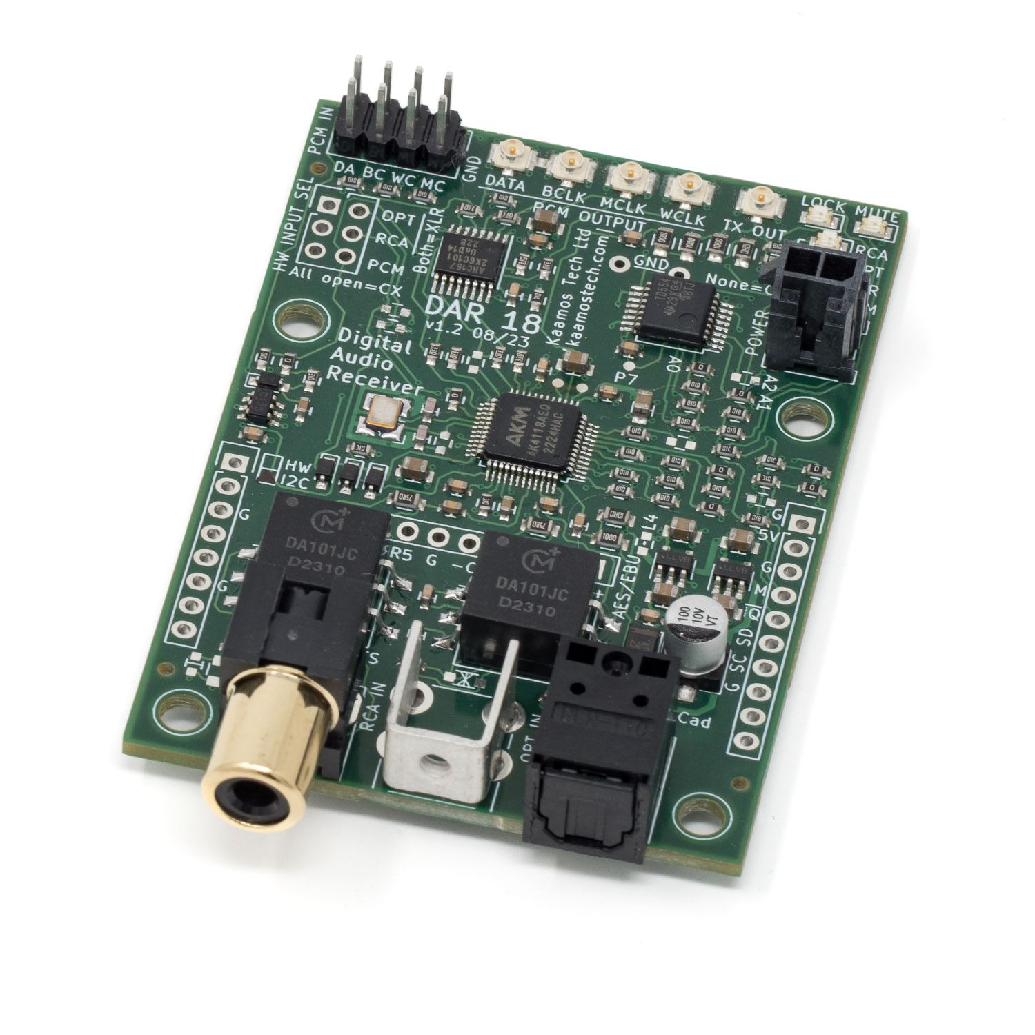
Following is additional information on using Kaamos DAR 18 board. Please also see the product description. If something is still unclear, please contact us. We will try to update the information based on feedback.
Power supply
The board only requires 5V for digital VD supply. This should not exceed 5.5V. You can use 2-pin Molex Micro-Fit connector with compatible Kaamos power supply, or cut and use the cable connected to your own power supply. Or you can just solder the supply wires.
Digital inputs
The board has RCA coaxial and optical Toslink S/PDIF inputs. To add more inputs, see below.
In addition, there is a PCM input via 0.1″ pinheader. When selected, this goes directly to I2S outputs via a switch. It allows the use of external USB or other module where I2S is just bypassed. The source must be I2S Master.
I2S signal outputs
DAR 18 has I2S digital serial output consisting of following four signals:
- MCLK – Master Clock
- BCLK – Bit Clock
- WCLK – Word Clock (sometimes also referred as LRCK)
- DATA
All these are outputs and provided with U.FL connectors. Signal level is 3.3V.
For information on using U.FL cables with headers, please see this post.
Mute
Mute (noted EMUTE on bottom silkscreen) on DAR 18 is active-high output that can be connected to W-DAC or any following circuit to mute analog outputs when there is no valid S/PDIF signal to prevent possible artefacts.
Briefly, whether using the board in HW or I2C mode, EMUTE output works even without any configuration or user interaction. However, below is additional information on the mute circuit details.
EMUTE generation in DAR 18 is a logical OR of three signals: AK4118A UNLOCK, AK4118A nAUDIO, and user controllable (via I2C) mute. When any of these are high, EMUTE is high. In HW control mode UNLOCK and nAUDIO take care that if S/PDIF receiver is unlocked or receives signal that is not PCM audio (e.g. accidental multichannel-coded S/PDIF), EMUTE is high. In I2C control mode UNLOCK and nAUDIO default to the same signals but these can be configured in AK4118A registers. In addition, user can set mute via TCA9554.
There are also onboard LEDs for LOCK and MUTE.
Extra I/O
DAR 18 has RCA and Toslink inputs onboard but there are several ways to add extra inputs. Officially we support up to 4 inputs in total but it is possible to use up to 8 in I2C control mode; please refer to AK4118A datasheet and DAR 18 schematics for connections. You do need external circuits for the inputs beyond four.
XLR AES/EBU input
There is already an input circuit for XLR input onboard so a panel XLR connector can be wired out without any extra components. When doing so, please do not connect XLR Pin1 to the PCB ground as it will direct interference picked up by the cable to the circuit ground. Instead, connect Pin1 to the chassis at the connector, or use a connector where this is done already (e.g. some Neutrik connectors).
We recommend using a twisted pair or microphone cable for the XLR pins 2 and 3 connecting to the PCB. If your cable has a shield, connect it only at one end (e.g. PCB ground, leaving the other end unconnected), again to prevent directing external cable shield interference to the circuit board.
XLR/BNC addon
We sell input addon board that adds XLR AES/EBU and BNC inputs; note that this XLR uses the same connection as the wired option mentioned above so you cannot use both.
BNC is electrically the same connection as RCA but it is a superior connector, albeit not widely used in audio. If you wish to use BNC to connect to RCA, you can easily find BNC-RCA adapters – or of course create your own custom cable using 75ohm coaxial cable and matching BNC and RCA connectors.
We can easily design other addon board options as well, e.g. to add extra Toslink connectors instead of XLR/BNC. If you have any wishes, please contact us.

S/PDIF output
There is also an S/PDIF output via U.FL, outputting re-clocked input signal. It may not be often needed but it is provided as the IC has the option. However, this is really only usable in I2C variant because in HW-variant the input cannot be changed but it is always the XLR.
Note that it is not possible to convert the PCM input to S/PDIF output.
Control mode variants
Two variants of DAR 18 are available, using HW-control or I2C control. The latter requires a host to program registers but HW-variant is as plug and play as it can be.
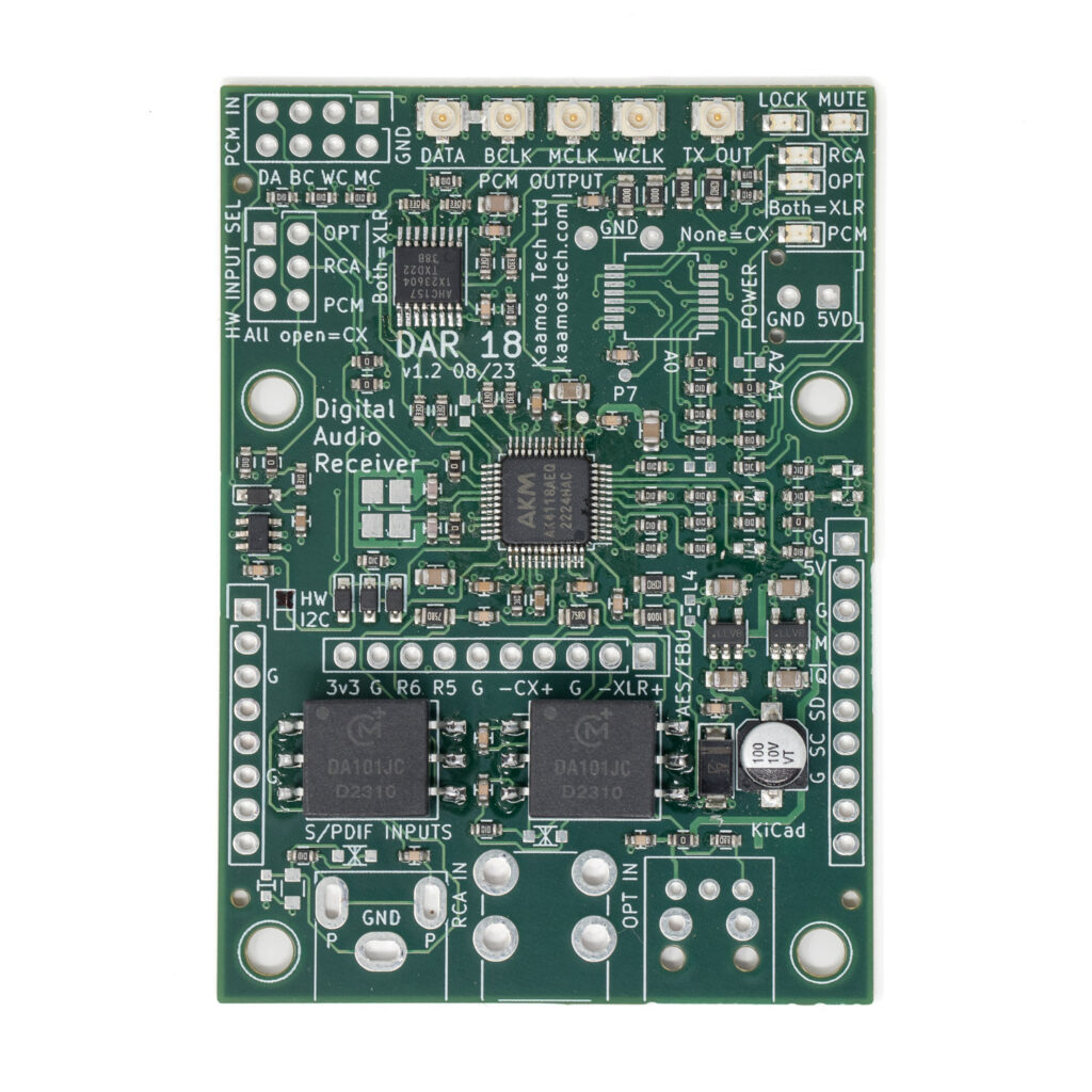
The PCB is the same for both variants but BOM is different. It is possible to convert the board between the two variants but it requires soldering/desoldering components, including ICs.
HW-control
In HW variant input is selected with jumper link:
| OPT jumper link | RCA jumper link | PCM jumper link | Input selected |
| closed | open | open | Optical |
| open | closed | open | RCA |
| don’t care | don’t care | closed | PCM |
| closed | closed | open | XLR (wired or adddon) |
| open | open | open | BNC (addon) |
RCA, OPT and PCM input LEDs work automatically when using jumper links.
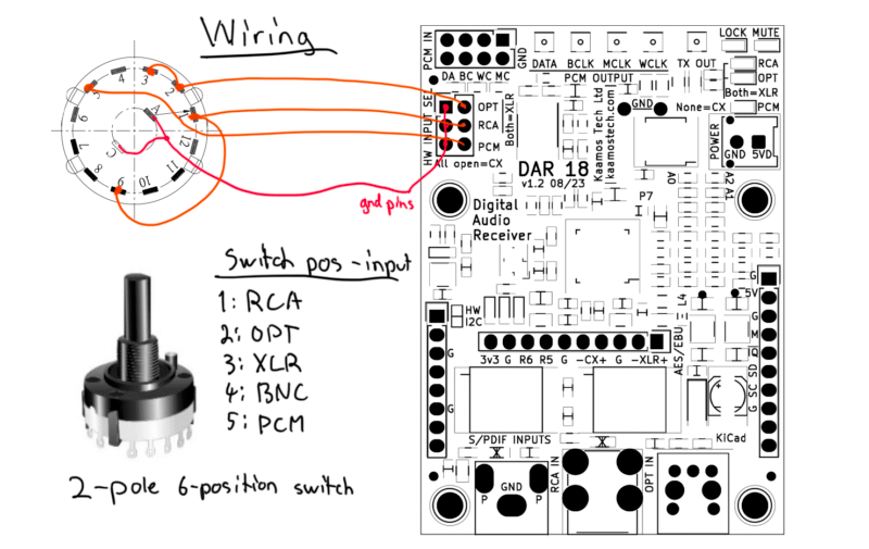
Using rotary switch to select inputs
You can add an external switch to select input on the HW-variant. Selecting between two inputs is simple with almost any switch, but it is also possible to select between all 5 inputs of a DAR 18 + XLR/BNC add-on combo (as shown in the photo above) with a widely available rotary switch. A wiring diagram is shown below. This type of rotary switches are available by multiple manufacturers in a range of styles and in the following configurations: 1-pole 12-position, 2-pole 6-position, 3-pole 4-position, and 4-pole 3-position. For this application the 2-pole 6-position is needed (the switch can be limited to 5-positions). The switch model we used to try this was Alpha SR2611F-0206-38R0B-D8-N.
I2C-control
There are two ICs onboard that needs to be programmed, otherwise the board will do nothing. Complete firmware is not provided but example register settings are provided below. It is simple to set up the board if you are familiar with I2C devices.
SDA and SCL needs to be connected for I2C. They have 10k pull-ups on W-DAC board but you may want to have stronger pull-ups close to Host – albeit this works fine at least with slower I2C speeds.
I2C addresses
The address formats and default 7-bit addresses for the two ICs are:
- AK4118A: 0010 0 A1 A0 RW (0x10)
- TCA9554: 0100 A2 A1 A0 RW (0x24)
A2, A1 and A0 are configurable by 0R resistors. By default A2 is unpopulated making it 1, and A1 and A0 are populated making them 0. RW bit is 0 for write and 1 for read as always in I2C.
Note that different AKM ICs use the same address format so if you have a DAC, ADC, and DAR 18 in the same I2C bus, make sure all boards use unique addresses.
Register programming
For details of the register settings see TCA9554 and AK4118A datasheets. However, a few code examples are provided below. Also find TCA9554 IO-extender noted as Px and how to configure them for different use cases.
TCA9554 controls PCM or S/PDIF input (P0), it also controls OPT and RCA LEDs as they don’t work automatically like in HW-mode. P3 is user-controllable input to EMUTE circuit. UNLOCK and nAUDIO signals (the same that control EMUTE) go to TCA9554 inputs and allows to use nIRQ to raise an interrupt at Host and respond by reading AK4118A what caused the UNLOCK and nAUDIO flag. In fact, these are called INT0 and INT1 in I2C-mode because user can control what internal signals flag them.
S/PDIF input is selected with AK4118A register 0x03.
var adExp = 0x24; // TCA9554
var adDir = 0x10; // AK4118A

// P0 = I2S_SEL; output selection: low=PCM bypass, high=AK4118A S/PDIF input
// P1 = nOUT_EN; I2S output: low=enable, high=disable
// P2 = RCA led; output, low=on, high=off
// P3 = EMUTE; output, high=mute (low is not necessarily unmute as it's OR of 3 signals)
// P4 = OPT led; output, low=on, high=off
// P5 = UNLOCK/INT0; input
// P6 = nAUDIO/INT1; input
// P7 = NC

// TCA9554
Write(adExp, 0x01, 0x91); // RCA SPDIF to Out (all still inputs)
Write(adExp, 0x03, 0x60); // P5-6 inputs, the rest outputs

// Alternatives to the first line
//Write(adExp, 0x01, 0x85); // OPT SPDIF to Out (just led change)
//Write(adExp, 0x01, 0x14); // External PCM input (AK4118A still enabled)
//Write(adExp, 0x01, 0x0F); // Mute high, output disable (AK4118A still enabled)

wait(1)


// AK4118A

Write(adDir, 0x00, 0x6B); // 512fs mode
Write(adDir, 0x01, 0x52); // 24b I2S, DEM disabled
Write(adDir, 0x02, 0x00); // Disable TX
Write(adDir, 0x03, 0x41); // 0x40=XLR, 0x41=RCA, 0x42=OPT, 0x43=CX, 0x44=RX4, etc

Write(adDir, 0x20, 0x3F); // Disable RX Input detect and power down oscillator
Performance tweaks
Seeing the AK4118A writes above, running the S/PDIF receiver in 512fs mode means MCLK is always 24.576MHz, whether the input sample rate is 48kHz or 192kHz. This ensures the best performance out of your DAC. For example, 64fs mode would generate only 6.144MHz MCLK with 48kHz sample rate which causes DAC performance degradation.
The last write is a result of lots of evaluation and needs a bit of explanation. First of all, the I2C-variant has a 24.576MHz oscillator onboard but the HW-variant does not. This oscillator has nothing to do with audio quality or clock recovery as it’s done solely by the PLL using the incoming S/PDIF stream. The oscillator is used for calculating input sample rate. Unfortunately, it also causes odd spikes in the FFT when connected to DAC. The same happens when the IC uses ‘RX Input Detect’ feature (some sort detection what input has signal coming in). Therefore, I have disabled the oscillator and this feature with the last line of code. However, when your Host microcontroller wants to read input sample rate, you need to enable the oscillator temporarily when reading the sample rate, and then disable it again. Please see AK4118A datasheet register map for how to do it.
To show the difference, below are two FFTs of DAR 18 prototype connected to W-DAC prototype, using RCA S/PDIF input and 48kHz sample rate. The level of the extra spurious components is just below the dominant harmonics and at -130dB you would never hear them; however, this one write does amazing job cleaning the FFT. Wish they would mention this in the datasheet because it took quite a while to figure this out by trial and error!
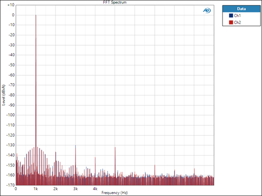
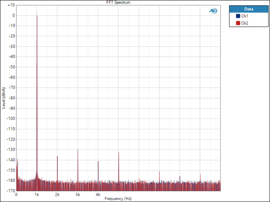
The above tweak only applies to I2C-variant. HW-variant has a clean FFT because it does not have the oscillator or RX Input Detect feature.
More information
See a post on connecting DAR 18 and W-DAC and DAR 18 product page.
10 comments
I like the hardware mode more,because I do not know anything about serial mode register coding..
But I also want to disable the “de-emphasis”(completely off).I think this is not possible with HW mode.So I can’t choose to use this board.I like the multiple input options a lot.But I imagined I can use a toggle switch directly on pcb,but it looks like controlling add-on inputs also not possible with this toggle switch.I don’t like the idea of changing inputs with extra cables.I like the output ufl connectors but also there can be a “standart” i2s out connector(together with ufl),extra choice can be good.Interesting but I couldn’t see the any jitter value on ak4118 datasheet,I think it is not important 🙂 Only ak4115 datasheet have jitter values.There are pages on the internet say wm8805 can be better for jitter.But I also don’t know how valid their datasheet jitter values.Some people also have 176.4khz freq problem with wm8805.I will not use but “Therefore, I have disabled the oscillator and this feature with the last line of code. However, when your Host microcontroller wants to read input sample rate, you need to enable the oscillator temporarily when reading the sample rate, and then disable it again.”,this is also sounds weird for me.I still don’t want to choose usb.
De-emphasis is always a bit odd one but I have never had any issues with several SPDIF ICs I have tried, I don’t think the status bits are really used in almost anything. But yes, it needs I2C mode to force it off.
As input control is binary, choosing between all inputs requires a bit more than just a toggle switch. It can be used between some inputs. I do recognise this is not ideal and I may look into adding some logic in the next revision (if there will be one) to allow use of a rotary switch.
I know UFL can divide opinions but it is for the best signal integrity. We sell adapter boards that can be fitted on pinheaders. Or you can do custom cables.
I considered WM ICs but did not use due to issues with recognising high sample rates.
The oscillator is only needed for reading the sample rate with microcontroller. If it’s on, it causes small deterioration in the signal as has been shown with measurements. That’s why the HW version doesn’t have it (it’s not needed) and in the I2C-version it should be turned off when not needed. This is of course not mentioned anywhere in the datasheet but was found in extensive measurements.
Can we change/adjust output audio data format in HW mode?(like 18 bit right justified).Is there a way to add led indicator to show de-emphasis is working(on-off) ? And is it easy to add something like multiple sample rate indicator leds to this board?Thanks.
The format is fixed to I2S in the HW-mode. You can do all that fairly easily in the I2C-mode with a microcontroller but not in the HW-mode.
Hi again.
ak4118 datasheet says “The pre-emphasis information is detected and reported on PEM bit. This information is extracted from channel 1 at default”. Does it mean channel 1 is RX1 ? So HW mode default de-emphasis is only for RX1? There isn’t de-emphasis for RX2 and RX3 in hw default mode? Thank you.
It means Left channel. You can also change it to Ch2/Right. It is taken from RX that is active and metadata decoded.
Can you design led sample rate indicator (AK4118 HAVE FS3-0 sampling frequency detection) or is it possible? similar to this add-on 14 led sample rate indicator board: https://www.diyinhk.com/shop/audio-kits/170-2324-xmos-32bit-384khz-dxd-dsd256-usb-tofrom-i2sdsdreclock-spdif-pcb.html#/97-oled_panel-null/107-led_pcb-null/141-fifo_option-null/151-usb_socket-type_c_new_and_slim/153-optical_spdif_output_socket-null
For now I am not doing microcontroller boards (which it would need) but leave it to the user to design the control and UI. Maybe one day.
Hi
There seem to be a market opportunity for this product as no S/PDIF output boards are available.
So, does the S/PDIF output provide a 3.3V signal level as required for the MiniDSP MiniSharc S/PDIF in?
Hi Lars. No, the signal is converted to around 500mV as per the nominal coaxial SPDIF signal (I should update the information). But it is 3.3V coming out of the IC so changing some of the SMD-components, you could easily get a 3.3V signal.