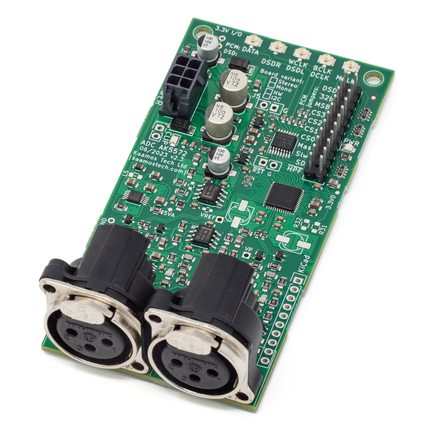
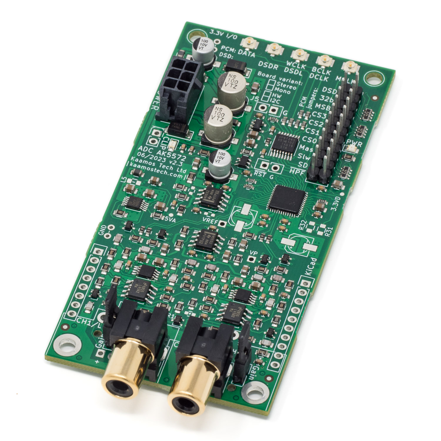
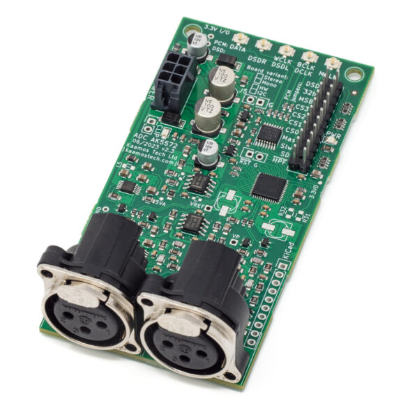
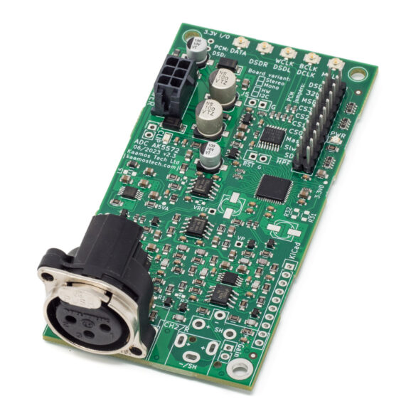
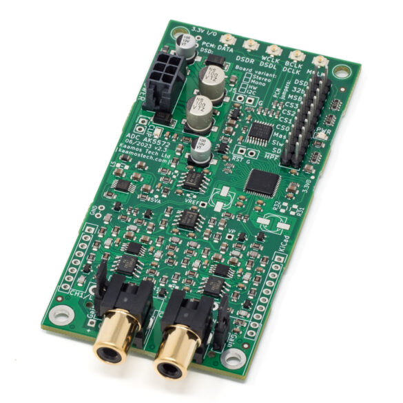
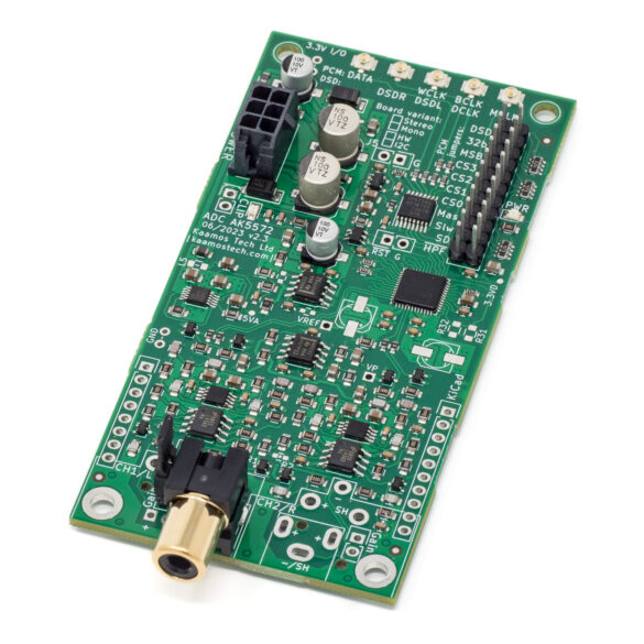
ADC AK5572 v2 -Very High Performance Audio AD-Converter
- Excellent performance, typical (balanced):
- 121 dBA dynamic range / SNR (124 dBA in mono mode)
- -114 dB THD+N (-1 dBFS, 1 kHz)
- -117 dB THD (-1 dBFS, 1 kHz)
- Up to 768 kHz / 32-bit sampling
- Stereo or mono operation, mono improves dynamic range by 3dB
- Two input options:
- Balanced XLR with 4 Vrms input level
- Single-ended RCA with 2 Vrms input level (THD 1-2dB higher than XLR)
- DC-coupled input (ADC IC has optional digital HPF to remove DC offset)
- AK5572EN, LM4562/OPA1632 opamps, LT3042 regulators, thin film resistors and C0G capacitors in audio path
- PCM (Master or Slave) or DSD (Master only) interface
- HW (jumper links) or I2C control
- Selectable digital filter and high-pass filter
- No back-drive via I/O by external clocks (new in v2.4)
- 4-layer 100mm x 50mm PCB
Requires following supplies (indicated max current):
- 5V for digital (15 mA)
- +/-15V for opamps; can be lower, e.g. +/-12V (70 mA each)
- 6V for DAC references (30 mA)
- This can also be taken from +15V (connecting outside the board or soldering ferrite beads or 0R on board; this increases VP current by 30 mA)
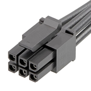
- All supplies provided via one 6-pin Molex Micro-Fit
Features
Both HW and I2C variant have identical performance and feature set is almost identical as well; see AK5572EN datasheet to make sure chosen mode and available settings meet your requirements.
HW-variant features
- Easy to use, no microcontroller needed
- All available settings are changed with jumper links on the 2×11 pinheader
I2C-variant features
- Needs I2C host, for example microcontroller
- Settings are changed via registers, see AK5572EN datasheet for register map; we do not provide a control firmware
Important information on order
- All SMD components are soldered down and the board is fully tested, connectors and headers are soldered if selected.
- Please ensure you have the skills to solder the remaining components and wires to connect the board in your system – and most of all understand what you are doing. Especially pay attention you have the correct power supplies and signal levels.
- Be careful with supply polarity and level, incorrect connections may destroy the board and/or your power supply.
- If you need help prior to purchase, please contact us.
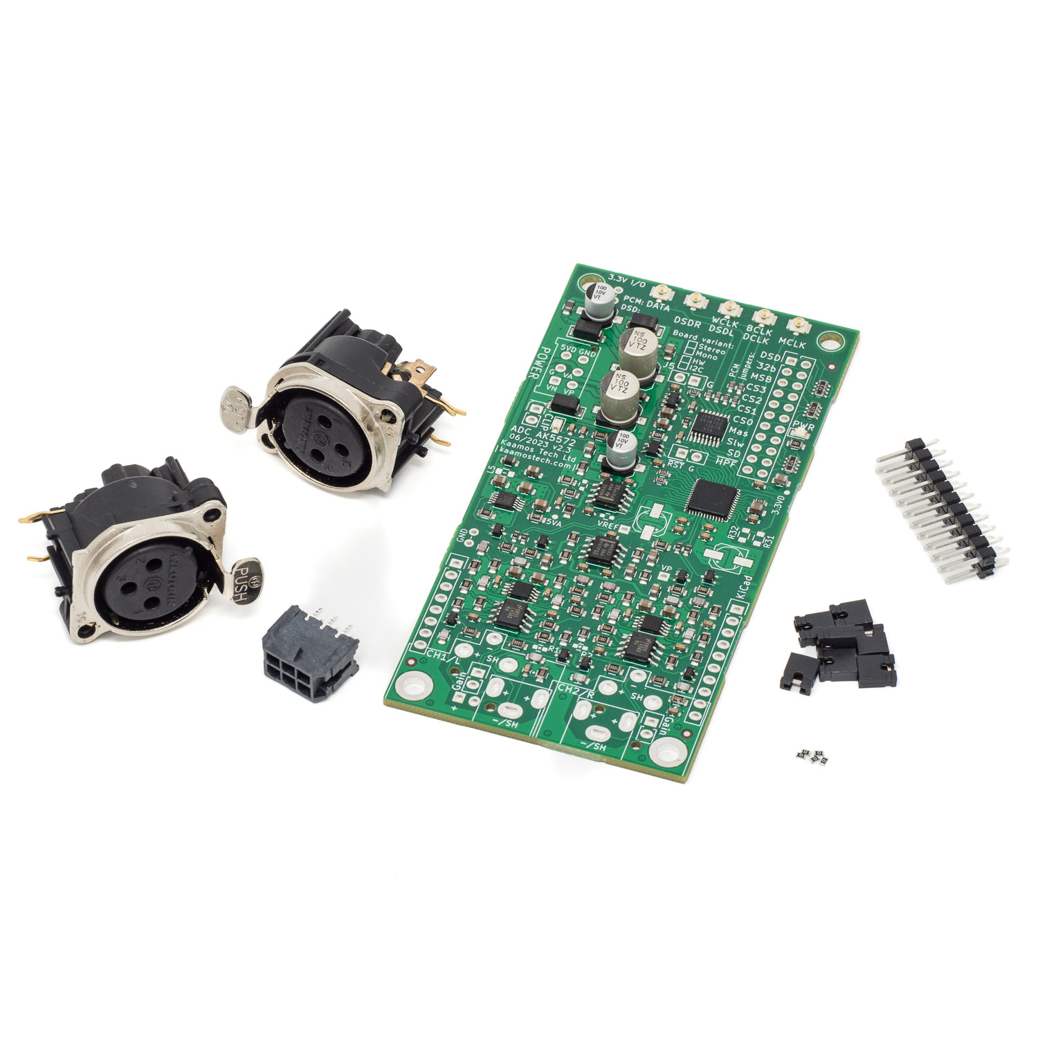
Order contents
List of what is included in the order:
- Fully tested board with all SMD components populated
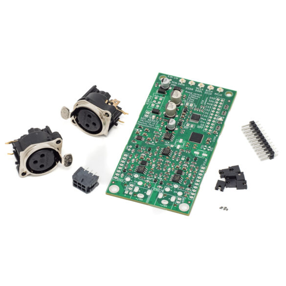
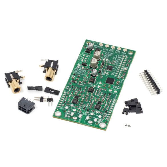
- 6-pin Molex power connector
- 2×11 male pinheader + 7 jumper links
- 0R resistors; depending on the options chosen some of them are soldered already
- XLR or RCA connectors if chosen in the options.
Photos
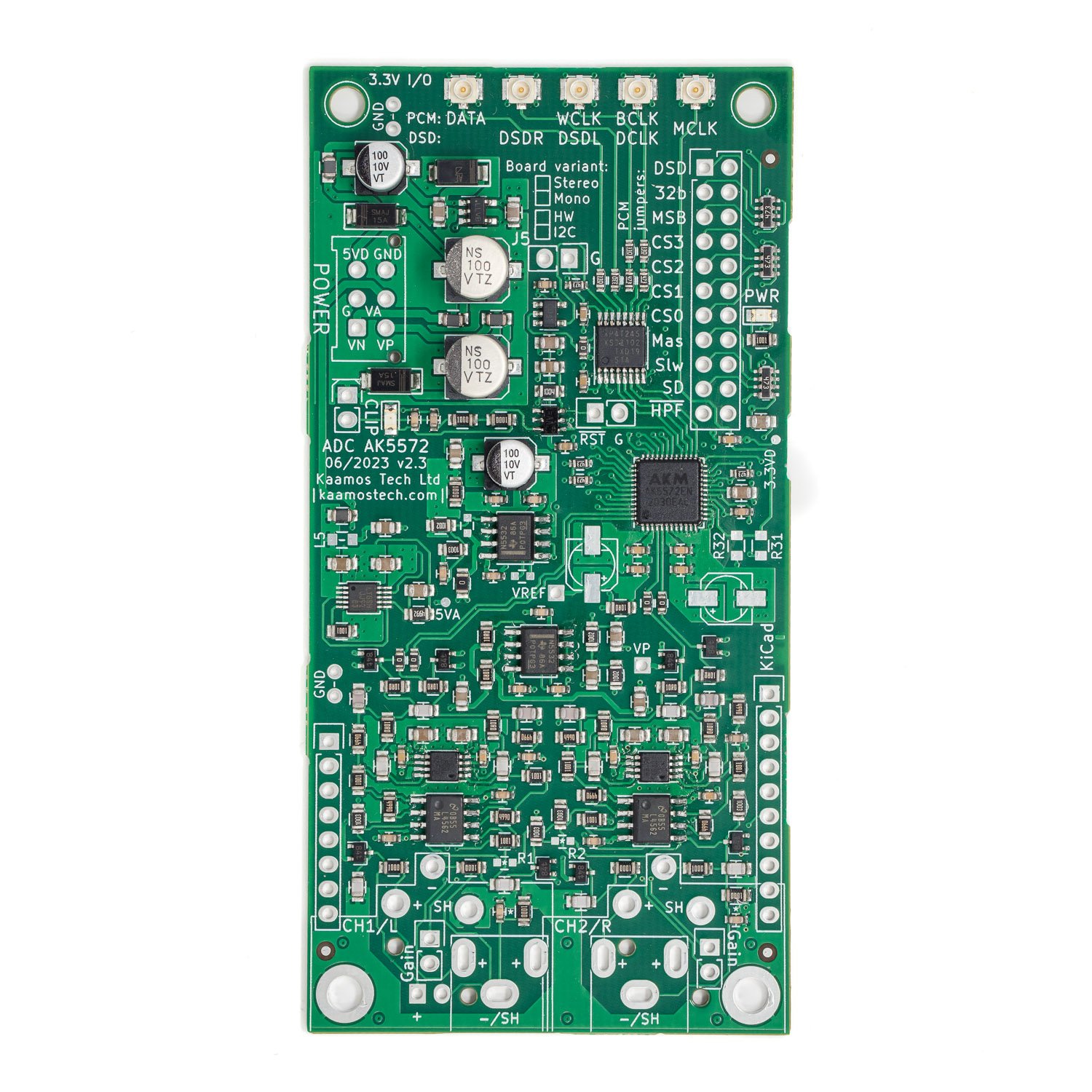
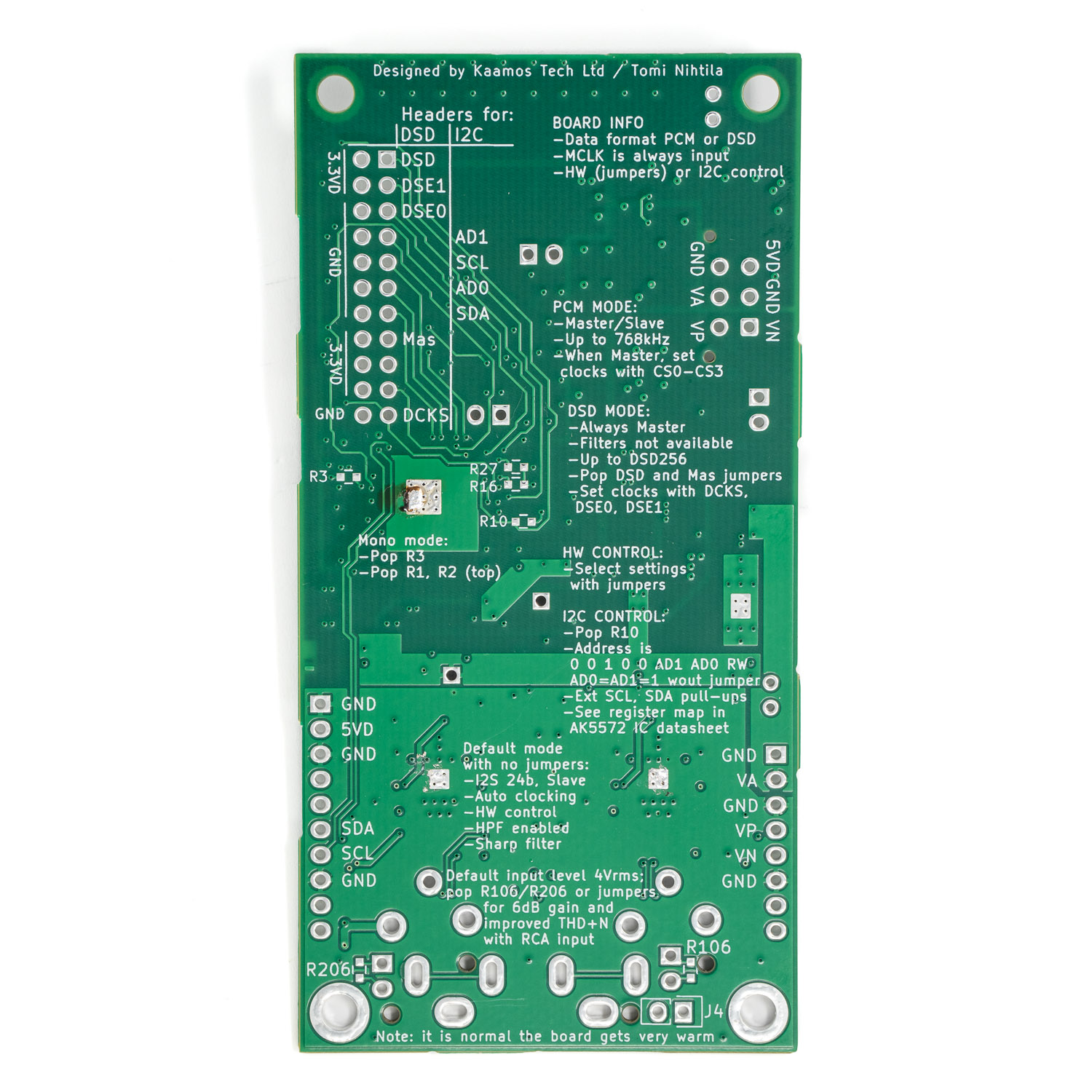
Photos of different variants.
More information
For more information on using the board, see ADC AK5572 v2 guide. There is also a post on how to connect ADC AK5572 and SPDIF TX.
For measurement results and version history, see the tab above.
There is also a video showing the board, its features, and how it is connected to other boards:
Files
- Schematics
- Component placement top (including board dimensions)
- Component placement bottom

