W-Output XLR v2 Standalone
Add XLR outputs to a device with only single-ended (RCA) outputs, or use as a fully differential buffer, for example adding a second XLR output pair.
- Independent fully differential output module from single-ended or differential input
- Excellent performance, typical figures for 2 Vrms input / 4 Vrms output
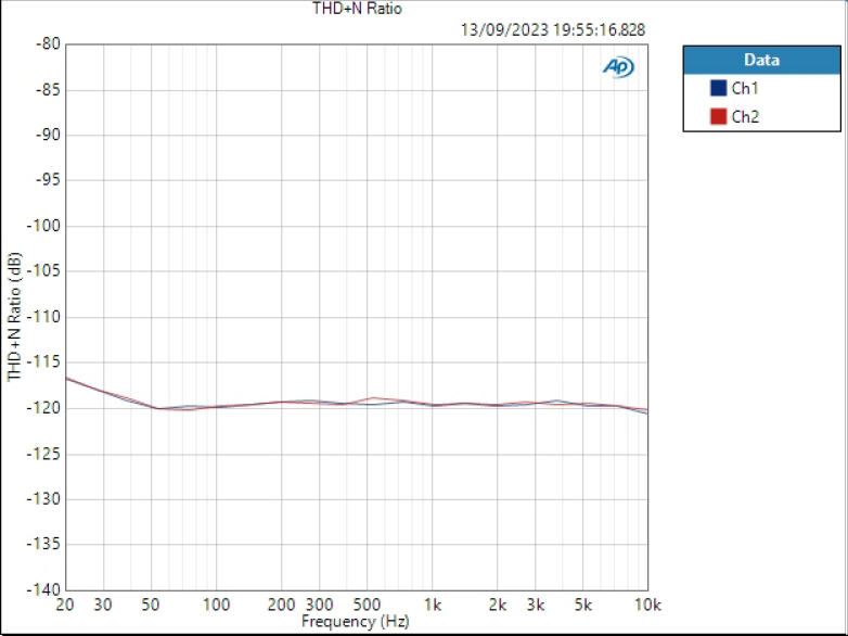
- THD+N ratio: -120 dB (1 kHz)
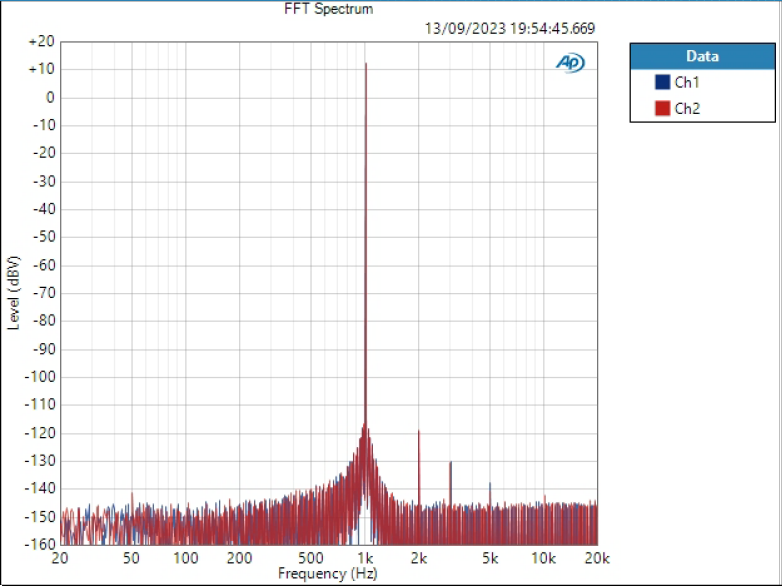
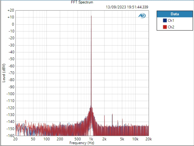
- THD ratio: < -130 dB (1 kHz)
- Dynamic range / SNR: 126 dBA
- Crosstalk: < -130 dB, 10 kHz
- High 100kohm input impedance does not load source circuit
- 6dB (2x) gain, more can be added by soldering one resistor per channel
- LM4562 buffers, OPA1632 fully differential amplifiers, thin film resistors and C0G capacitors in audio path, Neutrik XLRs
- Hardware output mute with relay
Requires following supplies (indicated max current):
- 5V (VD) for mute circuit (22 mA)
- +/-15V (VP/VN) for opamps; can be lower, e.g. +/-12V (52 mA per supply)
- All supplies provided via one 6-pin Molex Micro-Fit
Features
The simple circuit consists of LM4562 non-inverting buffers that can be turned into instrumentation amplifier with gain by soldering one resistor. This is followed by OPA1632 fully differential amplifier with 6dB gain. See schematics at the end of the page.
Input signal
Input is differential but works equally with single-ended input. Connect signal between + and -; GND is for shield only.
Mute circuit
Output mute relay shorts positive and negative outputs. It is normally closed and opens when VP/VN supplies exceed around +/-10V and 5VD is present.
MUTE input signal is an active high logic signal for the mute circuit. By default it is pulled low by R34 on bottom side of the PCB, meaning mute is released when the supplies are up.
Important information on order
- All SMD components are soldered down and the board is fully tested, connectors and headers are soldered if selected.
- Please ensure you have the skills to solder the remaining components and wires to connect the board in your system – and most of all understand what you are doing. Especially pay attention you have the correct power supplies and signal levels.
- Be careful with supply polarity and level, incorrect connections may damage the board and/or your power supply.
- If you need help prior to purchase, please contact us.
Order contents
- The board with all SMD components populated
- 2x Neutral XLR male connectors (if selected)
- Two 1×3 male headers for input signals
- 6-pin Molex power connector

Note: XLRs are only included if selected.
More information
If you need XLR outputs to W-DAC, please see the addon version of this board. It doesn’t have the input buffers and therefore has low input impedance.
Files
- Schematics
- Component placement top (including board dimensions)
- Component placement bottom


