
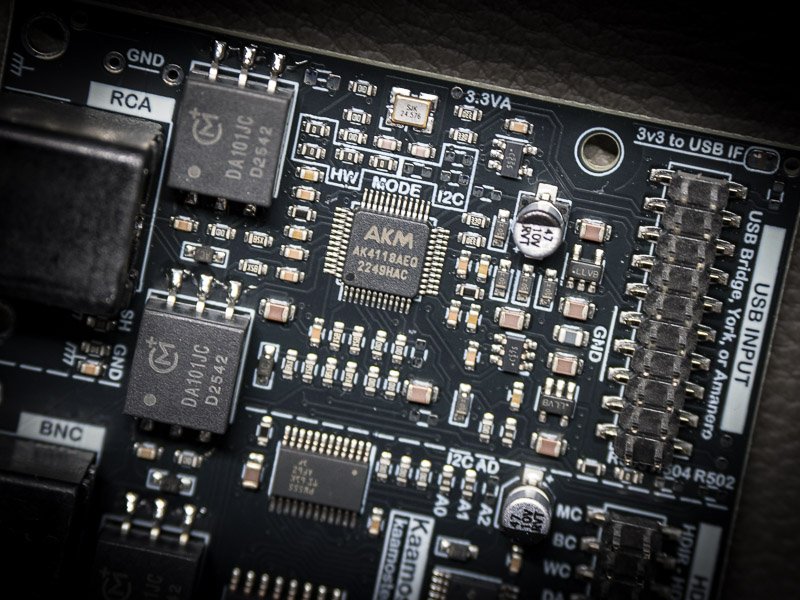
The AK4118A is a popular S/PDIF receiver, and we use it on the DAR 18 v2. With its default settings it adds spurs to the output that have nothing to do with the incoming signal. Two features are responsible: the crystal oscillator and RX input detect. Neither is needed to receive audio, and both can be turned off.
The short version:
| Control mode | What to do |
|---|---|
| HW (pin control) | Leave the crystal out and tie XTL1 and XTL0 high. |
| I2C or SPI (register control) | Write 0x3F to register 0x20 after every reset. This disables RX input detect and powers down the crystal oscillator. |
Below are two 1kHz FFT captures (64k points, 4 averages) showing the effect before and after the changes.
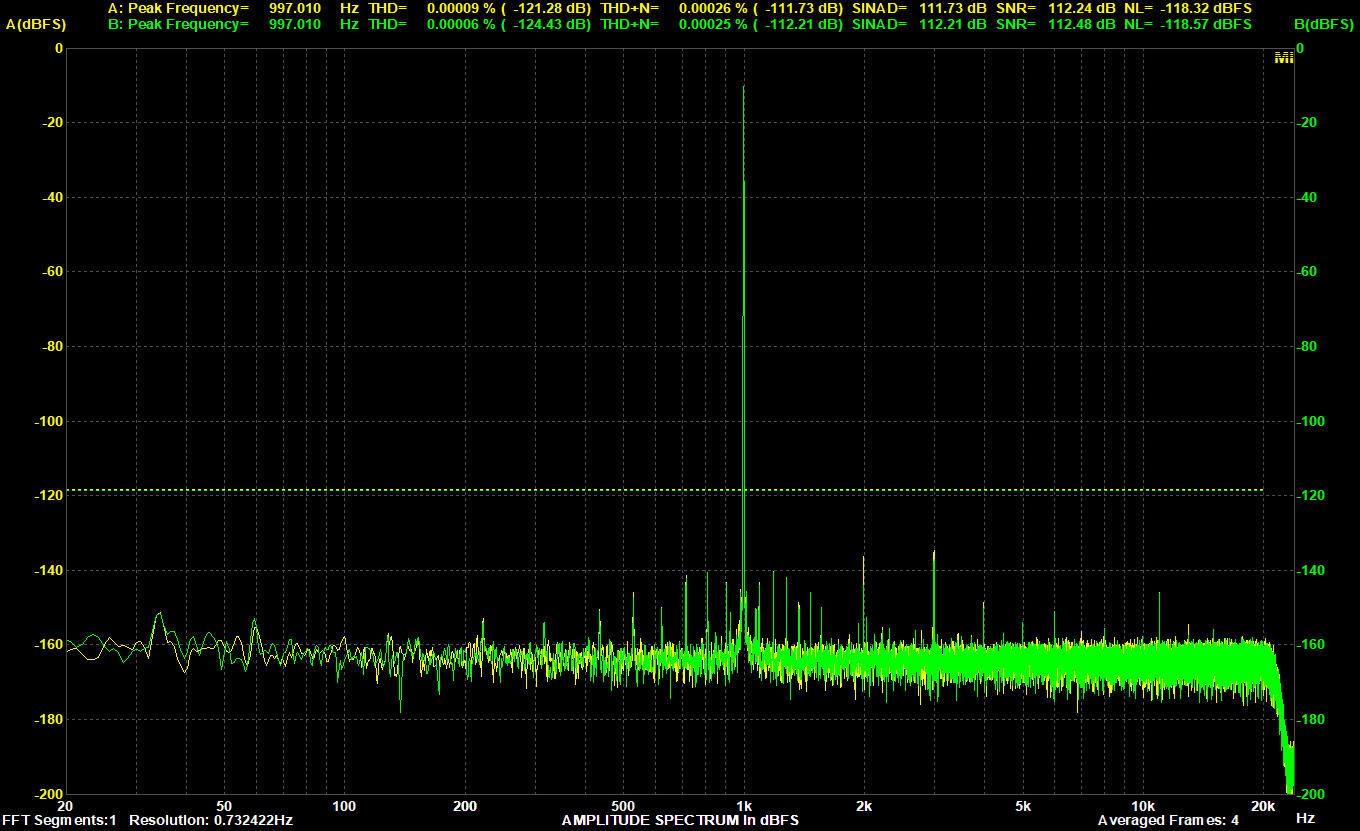
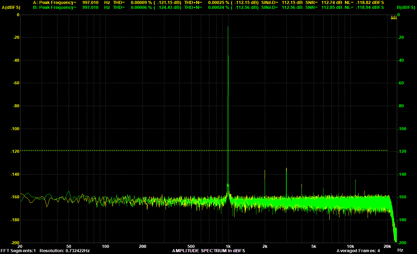
The rest of this post shows the measurements, explains what you give up, and covers the details that are easy to miss. The remaining FFTs are J-Test measurements, because the J-Test shows the effect more clearly and without harmonic distortion getting in the way.
What the J-Test shows
The J-Test is a digital test signal designed to provoke jitter on an S/PDIF link. At 48kHz it is a 12kHz tone (fs/4) plus a square wave at 250Hz (fs/192) in the least significant bit. The signal itself is very simple, so anything else that appears around the 12kHz tone on an FFT comes from the receiver and DAC. Symmetrical pairs of spurs (sidebands) around the tone point to deterministic jitter: clock timing errors that follow some repeating signal.
This makes the J-Test a good way to find periodic interference in a clock path, even when the levels involved are very low. The effect described here isn’t limited to the J-Test: the same spurs also show in an ordinary 1kHz FFT, just less clearly.
What the crystal oscillator actually does
A common assumption is that the receiver’s crystal has something to do with clock quality. In the normal receive mode it doesn’t. The AK4118A recovers its clocks from the incoming stream with an internal PLL, and the master clock, bit clock and word clock all follow that PLL.
According to the datasheet, the crystal has two uses:
- Clock source when the PLL isn’t used. Clock operation modes 1 to 3 use the crystal in place of the PLL, either always or when the PLL has lost lock. This determines what the I2S outputs do when there is no S/PDIF signal.
- Sample rate detection. The chip can compare the recovered clock against the crystal to work out the incoming sample rate, and reports the result in the FS3-0 bits of register
0x07. The result can only be read in register control mode.
Without the crystal oscillator, the outputs don’t stop when the receiver is unlocked. They carry low-frequency clocks from the free-running PLL: in our measurements MCLK was about 3MHz and the other clocks a few hundred kHz. The ratios between MCLK, BCLK and WCLK are still correct. AKM DACs seem to be fine with this, but some other DACs may not be, so check yours.
Clock mode 0, the default, uses the PLL only. A better crystal won’t improve the audio in this mode, and neither will a crystal at all.
Measurements
Test setup:
- S/PDIF transmitter: JLSounds I2SoverUSB-based DIY signal generator, coaxial S/PDIF output, 512fs MCLK.
- S/PDIF receiver: DAR 18 v2, coaxial S/PDIF input, 512fs MCLK.
- DAC: W-DAC v3.
- Measurement ADC: Cosmos ADC, set to 6.7Vrms input.
- Sample rate: 48kHz for all measurements, both for S/PDIF and the analog capture.
- J-Test FFT: 32768 points, 10 averages, 24 bits.
- 1kHz FFT: 65536 points, 4 averages.
The signal is measured in the analog domain, since that is the only way to see these imperfections. This means the S/PDIF transmitter, the DAC and the measurement ADC are all part of the signal chain. The results haven’t always been perfectly repeatable either, so treat small differences with caution.
All plots use the same setup and only the value of register 0x20 changes.
RX input detect on, crystal oscillator on (0x77, the default)
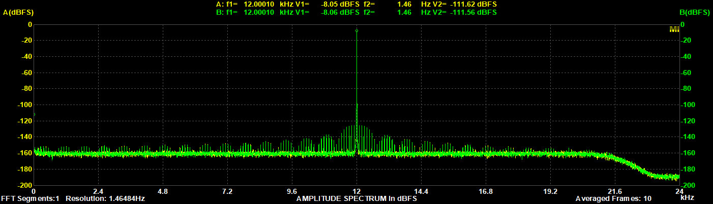
The highest spurs are a little above −120dB. Instead of a few sidebands close to the 12kHz tone, there is a spread of spurs across the whole audio band, falling off away from the tone in a roughly sinc-like pattern.
RX input detect off, crystal oscillator on (0x37)
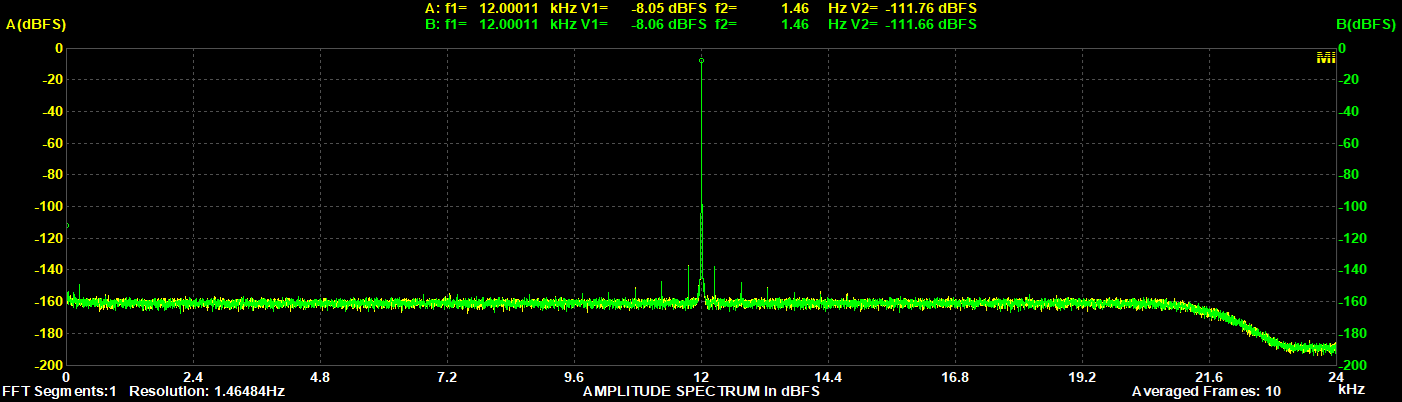
Turning off RX input detect removes the wide spread of spurs. On the DAR 18 v2, the only difference from the “both off” plot is a slightly wider skirt around the 12kHz tone. It is repeatable and also visible when zoomed in, as shown below.
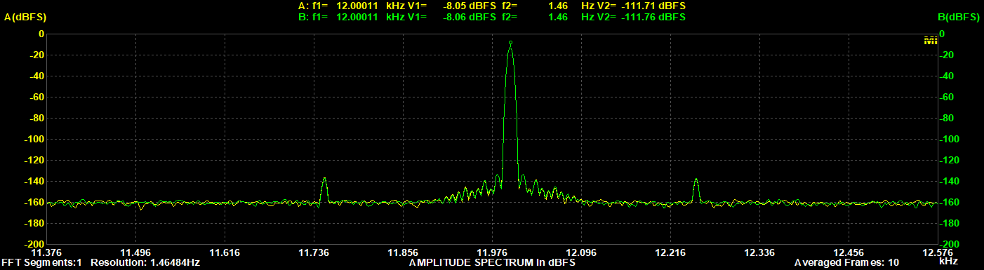
This case, with RX input detect off and the crystal oscillator on, also corresponds to HW (pin control) mode with a crystal fitted.
RX input detect off, crystal oscillator off (0x3F)
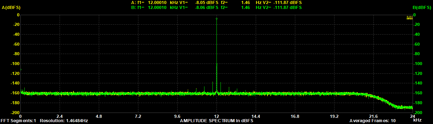
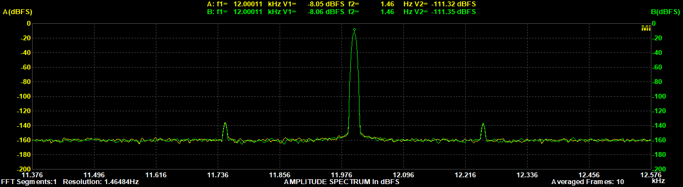
This is the best case. The highest spurs are around −130dB, with four visible on each side of the 12kHz tone, and the noise floor is at about −150dB. The remaining spurs most likely come from elsewhere in the AK4118A or the rest of the signal chain.
The same on a DAR 18 v1.3
The biggest improvement comes from disabling RX input detect. The effect of the crystal oscillator is less consistent, as our older DAR 18 v1.3 shows.
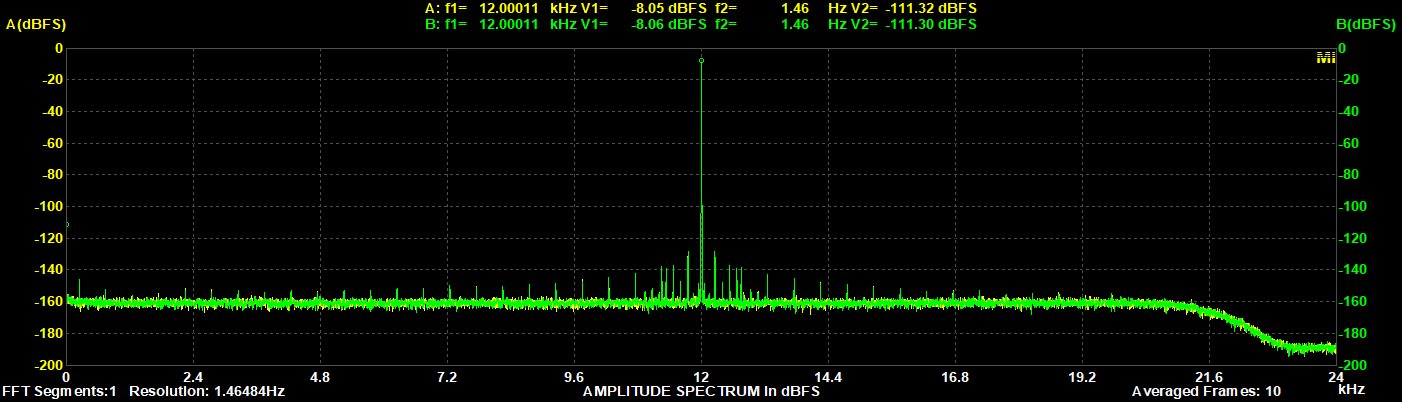
On the DAR 18 v1.3, with RX input detect off and the crystal oscillator on, there are extra spurs around the 12kHz tone that aren’t there with both features off. On this board the crystal oscillator clearly makes a bigger difference.
The circuit around the AK4118A is almost identical on the two boards. The v1.3 uses a different crystal part, although with the same frequency and package, so it should behave very similarly. The difference could come from the crystal, a small circuit difference or variation in the silicon. We haven’t investigated it further.
Either way, the conclusion is the same on both boards: the best measured performance comes with both features off.
Where do the spurs come from?
The datasheet doesn’t describe either effect, so what follows is our interpretation and not a documented mechanism.
Crystal oscillator: a running 24.576MHz oscillator shares the chip, and possibly supply and ground paths, with the PLL. It is an unrelated clock close to the sensitive clock recovery circuitry, so some coupling isn’t surprising. At 48kHz the 512fs recovered clock is also nominally 24.576MHz, the same frequency as the crystal. For the modes that use both clocks, the datasheet recommends that the crystal frequency differs from the recovered clock frequency.
RX input detect: this feature monitors the RX pins and reports which ones have a signal in register 0x25. The datasheet doesn’t explain how. Our best guess is that the detector does something periodic, perhaps scanning across the inputs, and that this activity modulates the recovered clock.
How much does it matter?
We don’t claim that spurs at −120dB to −130dB are audible. What we can say is that the difference is clear and measurable, and that the fix is a single register write or a few omitted parts. With a result this clear for so little effort (once you know about it!), we’re happy to take it.
It also means the measurements show the receiver’s real performance, not a side effect of features you may not be using.
This also shows up in commercial products
The pattern isn’t unique to DIY boards.
The issue has been discussed in DIYaudio threads such as Modular AK4490 DAC and Simultaneous output Frontend for TDA1541 (and or Universal Multibit DAC) using discrete logic. In the former, the thread starter, bohrok2610, confirmed the impact of the RX input detect feature on their own boards.
Besides DIY boards, the following commercial products have been identified as potentially having similar issues in Audio Science Review measurements:
We can’t confirm the cause in a commercial product from a plot alone, so take this as a similar pattern rather than proof. This is all (hopefully educated) guessing on our side, and we don’t have any inside information on these products. Some of the review threads do mention the AK4118 or AK4118A, though.
It’s surprising that the datasheet doesn’t mention this, as the effect is clearly visible in an FFT. It may simply have gone unnoticed: RX input detect is on by default, and there’s usually no reason to touch that register.
In the Modular AK4490 DAC thread, bohrok2610 also discussed how a sample rate converter such as the AK4137 effectively cleans up the J-Test spectrum. If you think Kaamos Tech should develop a hardware sample rate converter module, please leave a comment below.
How to do it
HW mode (pin control)
- Don’t fit the crystal, and tie XTL1 and XTL0 high. The datasheet confirms the crystal oscillator is off in this configuration.
- Keep clock mode 0 (CM1 and CM0 low), as the other modes need the crystal.
- There are no registers in this mode, so RX input detect can’t be controlled. Our HW-mode measurements without a crystal are as clean as I2C mode with both features off, so it doesn’t seem to be active in this mode.
- The MCLK setting made little difference in our measurements: 512fs and 128fs looked much the same.
Note that the DAR 18 v2 has the crystal fitted on both variants, as the HW and I2C variants share the same BOM. On the HW variant, the crystal is disconnected with 0R resistors.
I2C mode (register control)
Both controls are in register 0x20:
| Bit | Name | Default | Function |
|---|---|---|---|
| D6 | RXDETE | 1 | RX input detect. 0 = disabled. |
| D3 | EXCKMD | 0 | Crystal oscillator. 0 = powered up, 1 = powered down. |
Register 0x20 | RX input detect | Crystal oscillator |
|---|---|---|
0x77 (default) | On | On |
0x37 | Off | On |
0x3F | Off | Off |
These values leave the other bits in the register at their defaults. If your design changes any of them, change only D6 and D3.
A few things to watch for:
- Both features are on by default. A board that only writes the input select and audio format registers runs with both of them enabled.
- Reset undoes the setting. Taking PDN low or resetting via RSTN returns all registers to their defaults, so write
0x20again each time. On the DAR 18 v2 this also applies when switching back from a digital serial input, because selecting a serial input powers down the AK4118A. - Stay in clock mode 0. Modes 1 to 3 use the crystal as a clock source, so don’t power it down in those modes.
- RX detect flags stop working. With RXDETE at 0, register
0x25always reads 0. If your firmware uses these flags to select an input automatically, it needs another method, or RX input detect enabled only while searching for a signal. - Sample rate detection. If you want to read the sample rate, enable the crystal oscillator temporarily. Another option is to take the sample rate from the channel status in the S/PDIF stream, if the source sets it. This needs the XTL1 and XTL0 pins tied high, so it’s a hardware choice.
Summary
- The crystal doesn’t set the audio clock in the AK4118A’s default receive mode; the PLL does. The crystal isn’t needed to receive audio.
- With default settings, the crystal oscillator and especially RX input detect add spurs that are clearly visible in the J-Test, and also in a 1kHz FFT.
- Turning both off brings the highest J-Test spurs from just above −120dB to around −130dB, and removes the wide spread of spurs across the audio band.
- Leave the crystal out in HW mode. In I2C mode, write
0x3Fto register0x20after every reset. - Enable the crystal oscillator briefly when you need to read the sample rate.
The register settings are also in the DAR 18 v2 guide, and the schematics are published, so you can see how it’s all connected.