Following is additional information on using Kaamos W-DAC v3 board. Please also see the product description. If something is still unclear, please contact us. We will try to update the information based on feedback.
Power supply
The DAC board requires 5V for digital (VD, max 5.5V), 6V for analog references (VA), and +/-12…15V (VP/VN) for output stage. If you don’t have 6V references supply, you can solder an onboard ferrite or 0R resistor to take the reference supply from the VP (+12…15V), or just connect VP to VA outside the board; however be careful if using other Kaamos boards in the system as VP-VA connection may not be allowed in all boards.
See current consumption per supply on product page.
If you use a Kaamos power supply, all four supplies are provided in one 6-pin Molex Micro-Fit connector. If not, you can solder your own power supply wires in the Molex footprint or order a power cable, cut one end and connect it to your power supply.
PWR led indicates power is on.
W-DAC v3 also now has I/O back-power protection. In W-DAC v2/XLR, if I2S clocks are active before the board is powered up (e.g. always-on USB-module connected), the clocks partly power the DAC and cause it to not properly power up when the supplies are applied.
PCM/I2S signal inputs
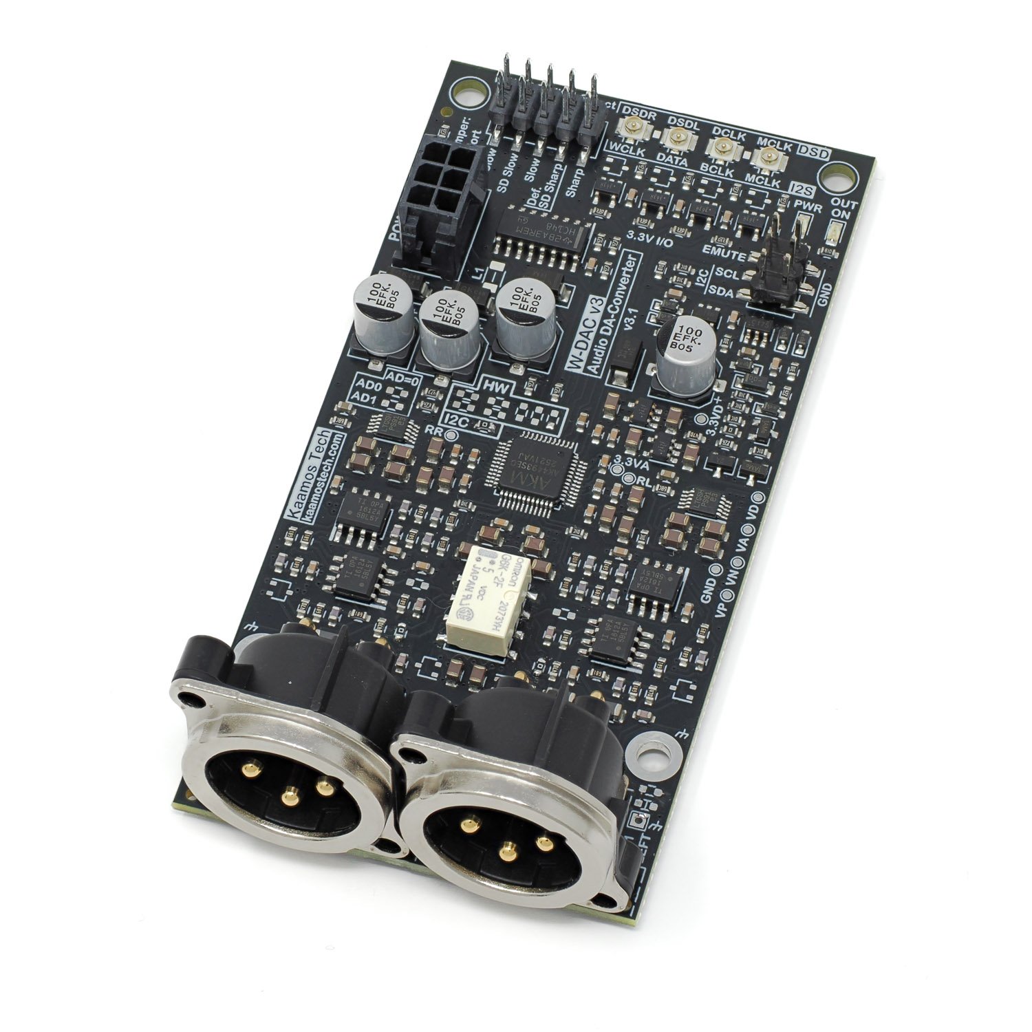
The default input for the DAC is PCM/I2S digital serial input consisting of the following four signals:
- MCLK – Master Clock
- BCLK – Bit Clock
- WCLK – Word Clock (sometimes also referred as LRCK)
- DATA
MCLK must be in sync with BCLK and WCLK.
All the signals are inputs and provided with U.FL connectors. Signal level is 3.3V and there is no termination. The same connectors are used in DSD mode; see below.
In I2C-mode other PCM formats than I2S are also supported.
For information on using U.FL cables with headers, please see this post.
Board signals
Signal names on silkscreen around power supply connector and edge headers:
- GND/G = ground (there is only one solid ground)
- VD = 5V digital supply
- VA = 6V analog reference supply (can be taken from VP if not available)
- VP = +12…15V output stage supply
- VN = -12…15V output stage supply
- EMUTE = External active-high mute input; the input is low (no mute) when not connected
- SDA = I2C data (I2C variant only)
- SCL = I2C clock (I2C variant only)
Mute
W-DAC v3 has automatic mute circuit that hard-mutes the output in any of the following situations:
- Supplies not up, simple monitoring of VD, VP, and VN.
- DAC IC in standby; no clocks or no references (VA).
- External EMUTE is high.
- Startup delay.
External EMUTE input allows the user to mute the output when EMUTE is high (3.3V nominal, 5V is also ok). When unconnected, it remains low.
OUT ON led indicates mute is off (output on).
Output filter
All DA-converters generate high-frequency image bands per Nyquist sampling theorem, and we want to filter them out. Non-oversampling DAC images are right above the audio band (20kHz+) and are difficult to filter out; it is technically inferior solution despite some audiophiles raving about them. Oversampling DACs such as AK4493S in W-DAC v3 push the images to higher frequencies (hundreds of kHz to low MHz) but they still need to be filtered out.
Oversampling DAC filter consists of analog and digital filters. The analog filter can be tuned for higher frequencies since it filters out the images of the oversampling, while the digital filter takes care of the band in between. For example, a DAC running at 48kHz has a real sample rate in multiple hundreds of kHz. The digital filter then takes care of the band between 24kHz and the Nyquist of the oversampling frequency.
Analog filter
W-DAC v3 has a third order Bessel filter at around 180kHz. Bessel filter is not the steepest type but it has superior phase and timing characteristics due to its constant group delay over frequency; it doesn’t cause phase/time related distortion of the signal and ringing is minimal. The filter is implemented within the OPA1612 opamp stages that also take care of gain.
Digital filter selection
Most DAC and ADC ICs offer selectable digital filters to fine-tune the response and sonic features. The impact of these filters on sound is minimal and in our opinion difficult to notice. Feel free to try. The default option by the chip manufacturer is Short Delay Sharp (SD Sharp). You can expect the Super Slow and Low Dispersion filters to be the most different from the usual sharp filters. The filter options are:
- Sharp
- Slow
- Short Delay Sharp (default)
- Short Delay Slow
- Super Slow
- Low Dispersion Short Delay
You can find the characteristics of the filters in the AK4493S datasheet. Note that these only apply to PCM inputs, not DSD.
In HW-variant the filter selection is done by “HW DAC Filter Select” jumper link or you can use a rotary switch to add the filter selection on the front panel. In I2C-variant the selection must be done via registers; the header is not populated since it is not functional.
A bit more on digital filters can be found on nihtila.com posts about PCM1794A filters and Audiolab M-DAC filters.
I2C variant information
The following information only applies to I2C variant of W-DAC v3.
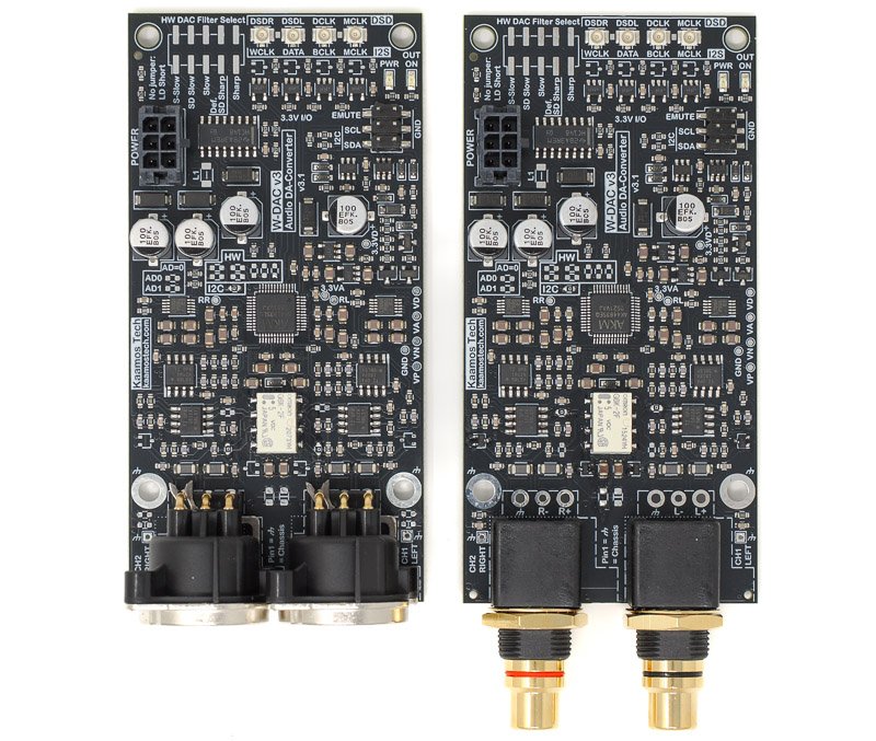
HW and I2C variants are the same PCB but use slightly different BOM. Near the DAC IC there are boxed resistors marked ‘HW’ and ‘I2C’; they are all 0R resistors and determine if the board operates as HW or I2C. Therefore, the mode can be changed.
The DAC IC registers need to be programmed (volatile, needs re-programmed after power toggle) to use the DAC, otherwise it will not do anything. Complete firmware is not provided but example register settings are provided below. It is simple to set up the board if you are familiar with I2C-devices, and in I2S mode only one register write is required.
SDA and SCL needs to be connected for I2C. They have 10k pull-ups on W-DAC board but you may want to have stronger pull-ups close to Host – albeit this works fine at least with slower I2C speeds.
I2C address
The default 7-bit I2C address of the DAC IC is
- AK4493: 0010 0 AD1 AD0 RW (0x13)
AD1 and AD0 are configurable by top-side 0R resistors near the DAC IC. By default these resistors are unpopulated, and in this default state AD1=1, AD0=1. Soldering the resistors invert the bits. RW bit is 0 for write and 1 for read as always in I2C.
Note that different AKM audio ICs use the same 2-bit address space so if you have a DAC, ADC, and S/PDIF to I2S in the same I2C bus, make sure all boards use unique addresses.
Register programming
For details of the register settings see AK4493S datasheet. However, a few code examples are provided below. Writing the following sequence configures the board to stream I2S-audio.
var adDac = 0x13; // AK4493S address

wait(1)      // There is a long nearly 1s power-up delay

// Write commands are Write(I2C address, register address, data)
Write(adDac, 0x00, 0x8F); // auto MCLK, 32-bit I2S, reset off

// Volume; optional, it is maximum by default
var vol = 0; // in dB

vol = 0xFF + 2*vol;
Write(adDac, 0x03, vol);
Write(adDac, 0x04, vol);
As seen, AK4493S only needs one register write to work with the default settings. In addition, you can change volume, digital filter, and lots of other settings.
DSD operation
DSD operation is only supported in I2C mode. This is a limitation of the DAC IC. Signal names are on silkscreen and use the same connectors as I2S:
- MCLK – Master Clock
- DCLK – DSD/Bit Clock
- DSDL – Left Data
- DSDR – Right Data
Please see AK4493S datasheet for setting up DSD, or have a look at our test code snippet below (which works for both DSD and I2S):
// DSD512 mode for DSD
Write(0x13, 0x06, 0x01);
Write(0x13, 0x09, 0x01);

// Automatic PCM/DSD switching
Write(0x13, 0x15, 0x80);

// Turn DAC on and set I2S mode for PCM
Write(0x13, 0x00, 0x8D);
TDM format
TDM format is also only available when using I2C configuration. There are multiple TDM modes so please refer to the datasheet. We have verified it functional with the following snipped using a USB-module in TDM256 (8ch) MSB format.
// TDM256 PCM
Write(0x13, 0x0A, 0x84);

// Turn DAC on and set MSB format
Write(0x13, 0x00, 0x8D);
More information
If you need more help, please contact us.