CCHD OSC Module – High-Performance Clock Oscillator Module
Clock oscillator module for DIY-builds or modifications.
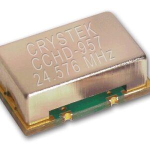
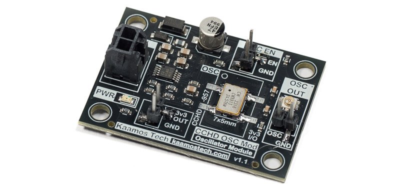
- Footprint for Crystek CCHD-957 or 7x5mm oscillator (oscillators sold separately).
- Very high-performance and low-noise LT3042 voltage regulator.
- Clock output via U.FL or pinheader.
- Oscillator Enable-header.
- Compact 43mm x 30mm 4-layer PCB.
Power supply requirements:
- Nominal 5V (from 4.5V up to 15V), 10-50mA.
- Current depends on oscillator type, clock frequency, and output loading. Typically it is around 20mA.
- Supply provided via 2-pin Molex Micro-Fit.
- If using a non-Kaamos power supply, we recommend purchasing a 2-pin Molex power cable, cutting one connector off, and soldering the wires to your own power supply.
Oscillator options
Connor Winfield CWX813 oscillator is good enough to hit the headline audio spec figures in our DAC and ADC tests.
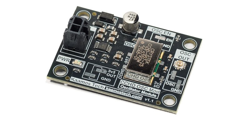
Crystek CCHD-957 is offered as a truly high-performance clock oscillator with significantly lower phase noise figures.
Extra headers
There are three 2-pin SMD-headers for extra options but they are not required.
OSC EN
Oscillator enable header disables the oscillator when shorted – if the oscillator supports EN-input (our oscillator options do).
3v3 OUT
Extra 3.3V output header allows connecting external circuits to the low-noise 3.3V source. The total current of the LT3042 voltage regulator is limited to 135mA which leaves around 100mA for external circuits. Practical limit depends on the input voltage. Keep the regulator power dissipation at maximum 1W.
OSC OUT
The main clock output is the U.FL which is at the end of the PCB-trace leaving the oscillator. However, very near that is an SMD-header which is an alternative for the clock output.
Do not populate the header if you don’t use it since it just adds an unnecessary stub on the clock line.
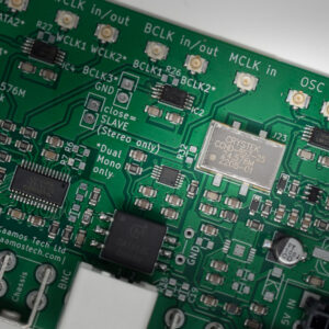
Note on clock domains
Please understand clocking before purchasing the module. In a typical audio system, all blocks must be synchronised, meaning they use the same clock domain. Therefore, in order to replace the clocking, you must be able to replace the sole Master Clock source all blocks are using. In some system this is not possible; for example, S/PDIF receiver extracts the MCLK from the incoming bit stream and this cannot be easily changed.
Important information on order
- All components (except optional 2-pin headers) are soldered down and the board is tested.
- By default the board is sold without oscillator. You can select an oscillator to be soldered down, or use your own.
- Please ensure you have the skills to connect the board in your system – and most of all understand what you are doing. Especially pay attention you have the correct power supplies and signal levels – incorrect connections may damage the board and/or your power supply.
- If you need help prior to purchase, please contact us.
Order contents
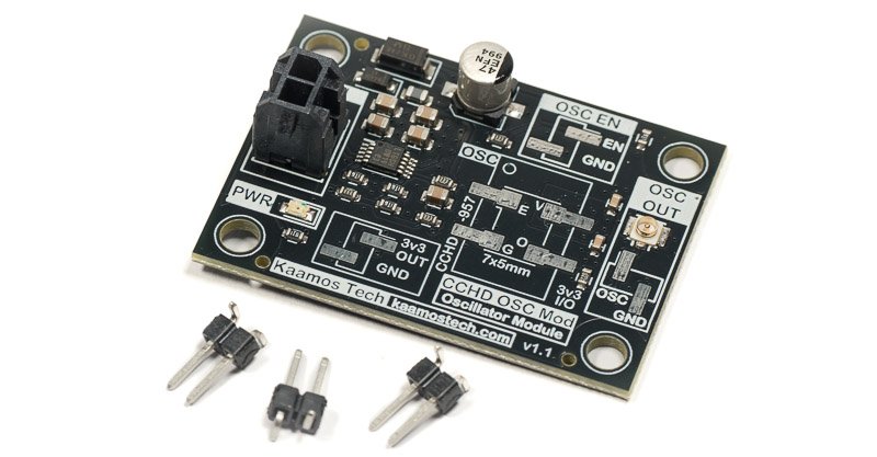
See contents in the photo below:
- Assembled and tested board.
- Optional oscillator also soldered if selected.
- 3pcs 1×2 male SMD-pinheader.
Please purchase power cable and UFL-cables separately.
Pair with Clock Buffer 1-4 for high-quality clock splitting.
Files
We do not guarantee the files are 100% match with the board. Especially when it comes to mechanical design based on the 3D-model, please verify any dimensions on an actual board since the model relies on 3rd party models we have not verified.
- Schematics
- Component placement (including board dimensions)
- 3D-model (.step)